Originally written and posted 2 June 2001.
Content last modified
Saturday, 9 January 2021
.
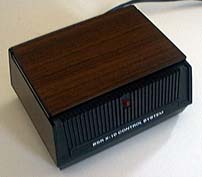
These are the tall, black and wood grain, original BSR System X10 (and related) controllers. Their closest modern relative in the X10 lineup is the SC503 Maxi Controller.
These command consoles feature 16 separate buttons for each of the X10 unit codes, plus On, Off, Bright, Dim, All Lights On, All Units Off. Most of the more modern controllers, esp. the mini controllers, have the On/Off function combined with the unit selection buttons, such that a single button push is all that is needed to activate or deactivate a module. While this older design requires pressing one or more unit codes, then a command, there are some advantages to this design. One huge advantage of this behavior in terms of testing and aligning X10 modules is that the PLC is generated continuously for as long as any button is held down. On many newer controllers, this facility is only available when there is a bright/dim function present.
The 542C ICs in my old CM14311 and CM14301 (before i char-broiled it) are identical in pinout and operation to the 78542 IC in my SC503. I found no IC differences whatsoever (outside of numbering and manufacturer), despite at least 14 years of age difference between the two generations of devices.
The only difference between the Ultrasonic CM14301 and the CM14311 is the presence or lack of ultrasonic remote control receiving circuitry.
There are any number of possible failure modes, so what i have listed below may easily NOT be what is wrong with your particular unit. I provide the information below here on this web page because i believe this to be the most common failure of the otherwise mostly reliable CM14301/11.
If the Command Console appears totally dead when tested:It is very common for the main electrolytic filter capacitors in the power supplies of most electronic equipment to fail. It seems especially common in X10 devices, given the high A.C. ripple, warm temperatures, and other demanding conditions the capacitors must endure. When in doubt, replacing any large (physically and value-wise) electrolytic capacitors (esp. 470µF or larger) may often cure problems.
In the 14 or so years before i recently let the “magic smoke” out of my Ultrasonic Command Console, i sometimes noticed occasional spontaneous LED flashes, or the appearance of the LED being stuck on, sometimes slightly dimly. These appear to have been problems related to the ultrasonic receiver circuitry picking up spurious high-frequency noises, such as the television or computer horizontal scan rate. Indeed, relocating this controller away from all sources of high-frequency noise reliably and repeatedly cured the problem.
I recommend the same cure to you. If you happen to have an otherwise-working Ultrasonic Command Console yet do not have and do not care to acquire any handheld ultrasonic remote control units, you could alternatively disable the ultrasonic receiver. The easiest way i see to do this is to disconnect the wire which leads to pin 7 of the IC from the collector of the 2N3904 transistor on the base PCB, and reattach it to circuit common. This is electrically the same as the non-Ultrasonic Command Console, and bypasses the entirety of the ultrasonic receive amplifier circuitry.
To ensure successful alignment, please be sure to read important information common to all X10 alignment procedures before proceeding.
Measuring the carrier frequency directly on these units will load and detune the oscillator excessively. Therefore, we use the knowledge that the 120kHz oscillator is divided down by 32 to 3.75kHz to drive the key matrix. By measuring 3.75kHz at the key matrix, we avoid loading and detuning the oscillator.
There is no adjustment in the Ultrasonic receiver circuitry of the CM14301. There is both a frequency and amplitude adjustment in the handheld remote control, and the best way to monitor these adjustments would be inside a CM14301. Since i blew up my only CM14301, you will not find any ultrasonic alignment procedure on these pages.
World O’ X10 ![]()
![]() The Sonically Pure Pages
The Sonically Pure Pages
This Siber-Sonically Pure Page is ![]() and
and ![]() Transitional compliant.
Transitional compliant.