RC5000 Wireless Remote Control System
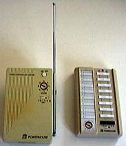
The RC5000 Wireless Remote Control System consists of the RR501 transceiver and the RT504 “Sixteen Plus” wireless remote control. Since the RT504 has very little circuitry and no adjustments, this page will mostly concern the RR501.
Schematics/Circuitry Differences
 IMPORTANT
: Apparently there are several distinct variations of the RR501, with very different circuitry. I discovered this while attempting to repair my father’s RR501 using Mitch Orysh’s RR501 schematic, and discovering that very little on that schematic matched the RR501 sitting in front of me. I wound up having to draw my own schematic by hand. Thanks to Mitch Orysh making his version of the RR501 schematic available, i was able to take his, modify it to match my father’s RR501, and post it here.
Identifying the Most Relevant Schematic
To determine if your RR501 matches mine, Mitch Orysh’s, or neither, check the following:
- Trace the module on/off push switch center conductor.
- If it connects to a 47kΩ resistor whose other end attaches to IC pin 10, follow Mitch Orysh’s schematic (Dead Link, left here for archive searching, but see the Schematics section just below for a copy on this site).
- If it connects to a 220Ω resistor labeled R1 whose other end attaches to IC pin 12, follow my schematic.
- If it connects in any other way, you have a variant which is currently undocumented.
- Count the number of adjustable coils/transformers not including the one in the large silver R.F. shielded box.
- If there are three, follow Mitch Orysh’s schematic.
- If there are four, follow my schematic.
- If there are more than four or fewer than three, you have a variant which is currently undocumented.
Schematics
My version of the RR501 schematic is available in two formats:
- as a GIF image of about 45k file size
- as an AppleWorks 5 drawing file, for MacOS users who wish to edit/modify the schematic. The file is compressed using the DropStuff 4.0 format, and is approx. 66k in size (and about 1.2MB expanded).
Due to the demise of Ido Bartana’s Home Automation Knowledge Base site and thanks to the efforts of site correspondent Bill W. for digging the file out of the Internet Archive—and of course thanks to Mitch Orysh for his original efforts—Revision H (newest known) is available here:
Please Please Please download the following PDF file rather than repeatedly viewing it from this site (if your device supports downloading)! (This should happen automatically in most cases as long as you/your device and software are not doing anything to override forced downloads.) This will help keep my WWW hosting costs low, allowing me to keep this site free and ad-free and donation request free. Thank you!
Mitch Orysh’s RR501 schematic, Rev. H (PDF download)
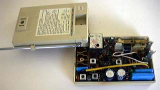
There’s a lot going on inside an RR501: R.F. reception at 310MHz, PLC reception and generation at 120kHz, PLC signal relaying, and a local appliance module latching relay to control. As such, there are several things to repair and adjust.
Repair of a Dead/Stuttering RR501
There are any number of possible failure modes, so what i have listed below may easily NOT be what is wrong with your particular unit. I provide the information below here on this web page because i believe this to be one of the more common failures of the RR501 Transceiver.
If one or more of the RR501 functions is inoperative and pressing the On/Off button produces a loud staccato stuttering sound:
- Unplug the transceiver and remove the two screws holding the cover together. Remove the PCB from the covers.
- Inspect the unit for visibly damaged parts. In the failure i found, the PCB will show signs of overheating near the power supply components, otherwise no damage will be visible. Replace any visually damaged parts and retest before proceeding. (There is nothing to be done about the overheated PCB itself).
- Locate a pair of large electrolytic capacitors along one edge. Value should be close to 1000µF at 25V. Replace them with a pair of the same value (slightly higher voltage and capacitance O.K. Try to maintain a match between the two). Carefully observe capacitor polarity!
- Dig through your surplus parts for some washers and rubber grommets to hold the PCB securely against the front cover, using the original screw(s). Reinstall the PCB into the front cover, ensuring that the button and switches are correctly positioned.
- Using a short length of extension cord, plug in the transceiver, and retest it.
- If it works, disconnect power and reassemble (or leave as-is for alignment) - you’re done. If not, further conventional troubleshooting will be required.
It is very common for the main electrolytic filter capacitors in the power supplies of most electronic equipment to fail. It seems especially common in X10 devices, given the high A.C. ripple, warm temperatures, and other demanding conditions the capacitors must endure. When in doubt, replacing any large (physically and value-wise) electrolytic capacitors (esp. 470µF or larger) may often cure problems.
What has happened in this case is that both the positive and negative power supply main filter capacitors have lost most of their capacitance. The power supply voltages have dropped, and have a huge A.C. component across them. Here is what i measured:
Peak-to-peak values were read off an oscilloscope screen. D.C. and Average A.C. values were from a Fluke 77 multimeter.
|
Before |
After |
| Positive supply |
≈+13VDC with ≈4Vp-p ripple |
+18.9VDC with .135VACavg/.44Vp-p ripple |
| Negative supply |
≈-13VDC with ≈4Vp-p ripple |
-19.5VDC with .11VACavg/.4Vp-p ripple |
RT504 Alignment
There are no adjustable components in a stock RT504.
RR501 Alignment
To ensure successful alignment, please be sure to read important information common to all X10 alignment procedures before proceeding.
Preparation for Adjustment
If you performed the repair described above, you’re all ready. Otherwise:
- Unplug the transceiver and remove the two screws holding the cover together. Remove the back cover (prong side).
- Dig through your surplus parts for some washers and rubber grommets to hold the PCB securely against the front cover, using the original screw(s). While it should not matter, i am not sure how the RR501 would behave with both unit code switch pins floating.
- Find a short length of extension cord to use to power up the RR501 in the following steps while still allowing access to the adjustments points.
CPU Clock Adjustment
Since, to the best of my knowledge, this adjustment does not affect the performance of the unit in terms of optimizing its interface with other X10 components in the outside world, i did not investigate any means of adjusting this setting (L7 on my father’s RR501 version). I left it at its factory setting and recommend that you do likewise.
R.F. Adjustment
- Locate the proper alignment tool to move the slug in the R.F. can without damage.
Note: adjustment is highly influenced by proximity effects. Use a long, good quality, properly fitting, nonmetallic alignment tool. Keep all body parts as far away from RR501 as possible. Monitor oscilloscope as you move to ensure there are no proximity effects affecting the adjustment.
- Connect 10X oscilloscope probe to collector of TR3 (i find the lead of C10 closest to the power relay to be convenient). Probe ground goes to circuit common, most conveniently the A.C. Hot prong.
- Position the rear cover rotated in such a way that the antenna is as close to its normal position near the R.F. plate as possible, yet the adjustment is accessible.
- Connect RR501 to isolation transformer. Power up.
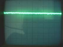
- With oscilloscope set for .1V/div.X10=1V/div. actual, and 2ms/div. sweep, one should see a noisy line (random noise) with a couple of volts positive D.C. offset:
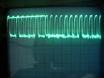
- Press and hold any button on your working, reference RT504. I use Dim.
- One should see the usual X10 pulse train riding on the noise:
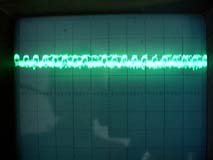
- Adjust for maximum response on a weak signal. While depressing an RT504 button and monitoring the oscilloscope, move the RT504 around, seeking R.F. null spots. Alternatively, insert the running RT504 in an empty metal coffee can (or similar), and move the RT504 and can around until a weak, yet visible signal is generated:
- Verify that the adjustment is still optimal when the alignment tool and your body are far removed from the RR501.
Note: Do not attempt to test R.F. range with the oscilloscope attached. The ’scope sufficiently loads the circuit and/or distorts the R.F. pattern that range tests will be disappointing and meaningless.
- Remove power from RR501. Fully disconnect oscilloscope.
- If tuning slug is loose, apply a dab of nail polish or your favorite removable thread locking chemical.
- With cover in, or close to, normal position (or 180° rotation), connect RR501 directly to powerline and test R.F. range.
PLC Output Frequency Adjustment
- Unplug the RR501. Jumper transistor T8 base to emitter to produce continuous 120kHz PLC out oscillation. (Connecting the end of R28 closest to TR8 to circuit common is the same as jumpering T8 B to E).
- Connect frequency counter to powerline signal sensor (not RR501). Power up counter and signal sensor, allow counter to stabilize.
- Power up RR501. Adjust L3 for 120kHz on counter.
- Disconnect all devices. If further alignment is to be performed, leave TR8 jumper in place, otherwise disconnect.
PLC Output Amplitude Adjustment
- Move the RR501 to the location where it will be used. Bring along oscilloscope and powerline signal sensor; connect these to a separate circuit, or at least an electrically distant outlet on the same circuit.
- Set up oscilloscope and powerline signal sensor to monitor the A.C. line.
- Connect RR501 directly to the A.C. line via the short extension cord.
- Adjust L2 for maximum 120kHz signal amplitude. This is likely to be a broad, “low-Q” peak.
- Unplug/disconnect all.
PLC Input Sensitivity Adjustment
- If the steps above have been skipped, move the RR501 to the location where it will be used. Bring along oscilloscope, isolation transformer (if needed), and previously calibrated controller of known correct frequency.
- Connect the reference controller to a separate circuit, or at least an electrically distant outlet on the same circuit, via some means of attenuating its 120kHz output (see the discussion in Common Points... for suggestions).
- Connect oscilloscope 10X probe across secondary of L1 (upper ends of D1 & D2 should work. Should measure ≈8Ω D.C. resistance). Oscilloscope must be isolated from the A.C. powerline, since module must be directly connected for best results. Avoid touching oscilloscope while module is powered.
- Connect RR501 directly to the A.C. line.
- Key reference controller to generate a continuous signal (Bright or Dim achieve this on most controllers so equipped).
- Inspect waveform. If there is clipping, reduce the amplitude of the signal from the controller until the displayed waveform is sinusoidal.
- Adjust L1 for maximum 120kHz signal amplitude. This is likely to be a broad, “low-Q” peak. If clipping occurs, further attenuate reference controller signal and continue adjustment.
- Unplug/disconnect all.
- Reassemble RR501 and test.
Questions/comments may be addressed to: Sonic Purity