Philips PM 3214 Oscilloscope Repair Notes
Comprehensive Repair Video
Not by me! YouTube user JoulesperCoulomb has made a comprehensive two-part video covering the troubleshooting and repairs he did on his PM3214 (link to Part 1). While there is only so much which can be covered in a bit under an hour of video (even when edited) on a device of this complexity, he covers quite a few topics of potential interest, including invaluable information regarding fixing broken push/pull switches on 4 of the pots, which i expand upon below.
I highly recommend this pair of videos.
Sonic’s Troubleshooting and Repair Notes
Display Dim, Long Warmup before trace is visible, Squeals
Recap the power supply, using good-quality electrolytic capacitors. This has given mine another 28+ years of life, so far (as of 2014).
Sweep Speeds from .5 msec and slower Don’t Work: they repeat .5µsec – .5msec
Found a bad solder joint on V1212, preventing it from switching C1206 3.3 µF capacitor (? this is from memory and cryptic notes from January 1987).
No/Insufficient/Intermittent Intensity Control
Part 1: Maybe with arcing sound or smell
Of course there can be many reasons for this set of symptoms. If the more common sorts of failures (component problems in the Intensity and related circuits) have been eliminated, knowing about the odd failure i eventually discovered and remedied may prove useful.
After spending all sorts of time carefully testing and troubleshooting, and eliminating all the usual suspects, i was left with anomalies such as all circuits and components appearing to work correctly, yet no intensity control and occasionally weird voltages at the CRT terminals. Cutting to the conclusion of weeks of troubleshooting, i discovered that the rubber gasket holding the CRT neck had become conductive! Indeed, removing the gasket and reassembling everything with temporary, or no, CRT neck support showed consistent normal operation.
It was easy to see the physical change in the rubber (shinier), and in some places measure finite resistance with a typical 10 MΩ input impedance DVM.
In the process of troubleshooting, i discovered some faint arcing between one or more socket contacts and the now-conductive rubber gasket. This could most easily (or only?) be seen looking at the socket from the side*, in a dark room, with the unit started up “cold”. The arc was small and continuously arcing (not pulsing) when it was happening. Whether this arcing was the cause of, result of, increasing, or unrelated to, the rubber gasket becoming conductive i do not know. On my PM 3214, the arcing seemed to settle down when the unit was warmed up.
With parts for this model not easy to find in 2005 (when this work was undertaken), the solution i chose was to remove the conductive rubber layer, exposing non-conductive rubber underneath. I do not know how long this repair will last… as i type this in 2008, the repair continues to “hold”.
Hopefully the successful resolution of my weeks of troubleshooting and puzzlement will save someone else similar efforts and lost time, and keep a decent analog oscilloscope productive and out of e-waste!
Part 2: No arcing, but basically the same problem
In the 2010 to 2014 time span, once again i had the following symptoms:
- Little to no intensity control, intermittently, failing to high/full intensity. Usually failing when first turned on. Gradually resumed normal operation if left on for one to several hours.
- No obvious failure in the intensity control circuit(s).
- No arcing (i am again running with the rubber gasket removed, to eliminate any possibility of trouble from it).
This repair is in progress as of summer 2014. I wanted to update this page to include information on the video(s) and the switch repair, and to let people know that i may have initially had two failures and only fixed one via rendering the rubber gasket non-conductive. I have not yet completed this repair. I hope to update this section once i have.
Push/Pull Switches on Some Potentiometers Lose Snap Action and Cease Switching
The switches in question are those on the backs of the potentiometers for Channel B Vertical Position (the Invert switch), Level/Slope for both the main and delay timebases, and X Position (the X magnification switch). I was unable to find anything online about these devices other than JoulesperCoulomb’s video(s).
This may be a common failure, based upon both my and JoulesperCoulomb’s PM3214s having suffered this failure. I am indebted to JoulesperCoulomb for presenting his important findings in Part 1 of his two-part video, though even with his information and the brief image of the partially assembled switch, i was still unable to enact a fix. Here’s my version of the repair, with text and still images instead of voice and video.
It is possible (and recommended) to remove the whole switch/control assembly from the oscilloscope frame as a unit. This is an elaborate process which is covered in the manual (combined user/service manual. Many paragraphs and pictures) and will not be covered here. This isn’t going to be a fast repair: expect to spend half a day if you’re an expert and a full day or longer if you’re not.
We skip ahead to the point where the pot/switch has been removed from the assembly, and the 4 metal tangs holding the plastic switch housing to the back of the pot have been bent outward to allow the housing to be removed. If one removes the housing carefully, one will likely see something like this:
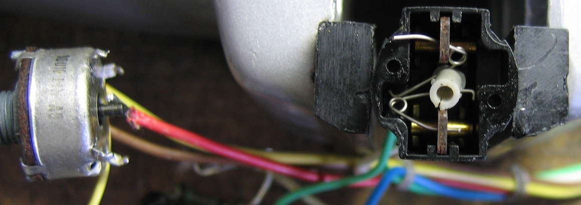
Here we see the bottom over-center spring in its proper operating position, and the upper spring having slipped out of position—but that’s not the failure. See the crack on the gray plastic actuator?—that’s the failure: it is supposed to be rigidly attached to the black shaft coming out of the back of the pot. Here’s a side view of the actuator with crack:
The easy part of the repair is putting a drop of cyanoacrylate adhesive onto the tip of the metal shaft of the pot and then immediately pushing the cracked gray plastic actuator all the way on. The top of the actuator is not perfectly round—two opposing sides stick out more than the two perpendicular sides—yet i did not find the alignment to be critical, since one can rotate the pot to have the sides which stick out more or less facing the spring surfaces during reassembly as one wishes. There is a groove all the way around the actuator in which the springs ride in normal operation, as clearly seen in the image immediately above.
Only time will tell whether cyanoacrylate is a long-lasting repair choice. So far, so good. Allow plenty of time for the actuator-shaft bond to set.
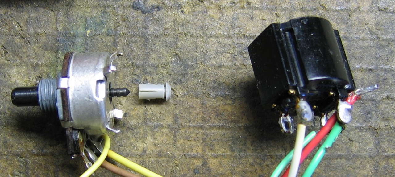
While the actuator bond is setting up is an excellent time to clean the switch contacts and study the pieces, in preparation for reassembly. Here’s a view with the newly-glued actuator and the other parts of the disassembled switch:
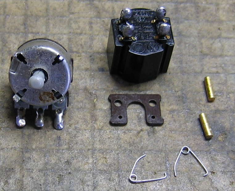
Although the switch cover appears symmetrical, the printing is meant to be read with the pot contacts facing downward, as shown in the photo. Looking back at the first photo, one might assume that the way to reassemble the switch is to slide the phenolic contact carrier/insulator assembly into the plastic housing, then somehow engage the springs. If there is a way to do that, i didn’t figure it out. I was totally stumped until finding JoulesperCoulomb’s video (part 1), showing the contact carrier standing on edge on the back of the pot, with the springs engaged and the contacts sitting in place in the carrier.
Once the actuator was firmly bonded to the pot shaft, i attempted to replicate what i saw in JoulesperCoulomb’s video, failing and eventually giving up for the day in frustration. If you’re the sort of person who enjoys stacking playing cards into structures as tall as yourself and does well at it, you might find it easy to keep the carrier standing on-edge as the springs are positioned and contacts inserted. I am not such a person, so i needed to figure out another way.
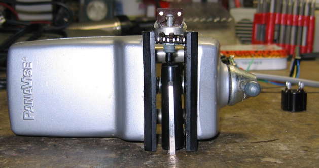
If there were some way i could fix the board in place whilst i inserted the springs and contacts and later remove the added support, i figured i’d be able to reassemble the switch. I found such a way: hot-gluing the edges of the contact carrier to the back of the pot:
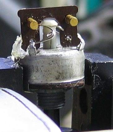
Even with the hot glue, since it is only on the edges i still needed to be careful and support the board when inserting the springs. Note that the right angle hooked end of each spring rides in the actuator groove, and that the straight end of the spring goes through the small hole on the carrier. Here’s a top view:
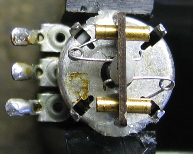
The top view clearly shows how “far” in/out the springs need to be inserted, especially at the top where they contact the actuator. This photo does not show their penetration through the carrier, and the side view above is also less than informative. Approximately 2 to 3 mm of penetration of the straight tip of the spring past the phenolic contact carrier is about ideal. Too far in (towards pot center) and the spring will become unstable and pop through. Too far out and the spring loops will hit the housing and not fit. When looking straight down as in the photo immediately above, the loops need to be over the back of the pot, not overhanging beyond. The bottom spring in the top-most photo in this section shows optimal penetration of the straight end of the spring.
One potential frustration when inserting the springs is the tendency for the actuator/shaft to slide around. I mitigated this by using something (a pen cap) to keep the shaft pushed all the way in:
Once all the parts are in place, carefully slide the switch housing over the top of the contact carrier, ensuring that the carrier engages the grooves of the housing correctly. Slide the housing down until it is stopped by the hot glue blobs. Carefully snap off each hot glue blob and lower the housing the rest of the way. Hold the housing firmly in place as you test the mechanical action, then the contact resistance/switching action of each of the two switch sections (double pole single throw, contacts both closed when pot shaft is pulled out). Once you are satisfied that the switch is again working properly, bend each of the four metal tabs back into place to securely hold the switch housing. Done!—repeat for the other pot switches, and reassemble & test everything.
* Left side, relative to viewing ’scope front, in my case.