Telephone Ring Generator
The circuit is a telephone ringing signal generator, for testing, chime modification, and possibly someday daily operation of old-style mechanical telephone ringers used in North America.
Excluding the power supply, there are three blocks:
- 555-based Gating Oscillator
- 741 op-amp-based Wein bridge oscillator, adjustable from 20Hz to 68Hz (for harmonic ringers)
- IC power amplifier for driving the ringer coil(s)
Per what i have read of North America telco specs, the output needs to be 20 to 68Hz at 40 to 150VRMS and up to 20mARMS (about 79 mA peak) to cover the various mechanical ringers made over the years and varying line conditions. This unit is continuously adjustable from 14 to 69 Hz and 0 to 117VRMS. Under some conditions, there may be clipping between 110 and 117VRMS (red area of the level adjustment potentiometer range).
The circuit is designed to be connected to standard telco inside wiring and drive the usual household ringer assortment, in the future when analog phone service disappears. At that time, the power amp may need to be modified to provide a D.C. offset of -48V, to supply talk battery.
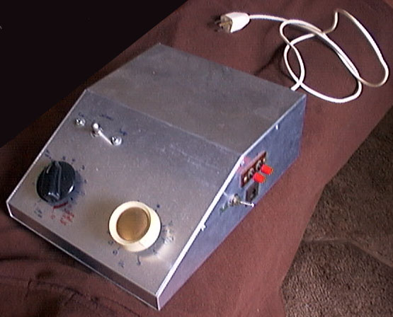
The 3-position toggle switch (on the front of the prototype) selects between Standby, Continuous, and the normal Gated Ring Cycle. The Continuous option is available for peaking mechanical response at a given frequency
Output is available at both a pair of screw terminals and a standard RJ-11 modular jack. The switch on the side near these items switches between the (normal) green and (unusual) yellow leads of the modular jack. This is a personal adaptation, to accommodate the many phones in my household with one end of the ringer attached to the yellow lead (i use this to switch on and off all ringers in the house from one switch).
Junk box parts were used wherever possible. Many component values were chosen with stock-on-hand in mind, and may be modified with no detrimental effects.
Acknowledgements
My thanks go out to the participants of sci.electronics.design circa Oct.-Nov. 2000, especially George Kinder and Mike Wu, for the many suggestions and ideas that led to the final power amplifier section design. Originally, i was trying to design a discrete power amp section. Lack of experience and the ready availability of the Apex PA 44 led me to “wuss out” and use this appropriate IC instead.