iPod Mini CompactFlash Modification Tips
This page is intended as a summary of best practices for either or both of replacing an iPod Mini battery and/or swapping the stock miniature hard drive for a standard CompactFlash (CF) memory card. It is aimed at skilled hobbyists who are good with their hands, who really only need a few essential tips and can benefit from my mistakes and knowing what to expect before they dig into their Mini.
This page is not intended as a comprehensive discussion of either battery replacement or the CF mod, both of which are covered very well already elsewhere on the WWW. It is intended as a fairly decent meta-summary of the information out there, at least through the most recent modification date of this page, and as an adjunct to the other information resources for “gotcha” information not (well) covered elsewhere. If you’ve not already done some reading on the subject elsewhere, i suggest starting with:
Disassembly and Internal Workings Notes
Just so you know with whom you’re dealing here, i am not generally regarded as a ham-fisted doof. Probably like you, i’m an electronics hobbyist, with (in my case) decades of hands-on hardware experience. One former career was as a home audio (“stereo”) equipment repair technician (15 years, ’80s and 1st. half of the ’90s), where i occasionally did “heroic” repairs which included resoldering very fine wires. I’ve built my own active SCSI terminator, repaired hard drives by opening them up and doing mechanical work, and more. Not always successful, yet usually. Despite my years of experience, i still managed to really mess up my True Love’s 2nd. generation iPod Mini. Had i known what i’m about to share with you, the problems would not have happened.
Disassembly Notes
Nearly all information sources clearly let us all know that the white end caps are held on with adhesive. Some note that it is easy to mess up the aluminum case, which i certainly did. Few if any note the following, or if they do so note, do not sufficiently emphasize:
- The plastic end cap adhesive comes off more easily with heat
- Be sure to heat up the end caps with a hair dryer or similar, to make removal easier.
- The plastic end pieces are approximately 1 (top) to 1.5 (bottom) mm thick
- At first, i thought they were very thin stick-on films. I was prying near the surface, very nicely chewing up the plastic, and getting nowhere. Then i started digging down deeper… so deep in fact that i snagged the metal headphone jack/hold switch frame (top side). I kept prying against that frame, very nicely mangling the aluminum case. I was literally in too deep!
- There are good and bad places around the circumference of the white plastic end pieces from which to pry/not pry
- These are discussed and illustrated below.
- Use a plastic prying tool. Really.
- Yes, the prying can be done with a metal tool (i did, and have plenty of scratches and bending to show for it). It will be easier with a good plastic tool. One source recommends a guitar pick, which seems like an excellent choice.
Be sure to pry down deep enough, yet not too deep, and in the correct places. For the bottom end piece (dock connector end), there is a rim halfway across the thickness of the plastic piece, about .75 mm down, so target for that prying depth.
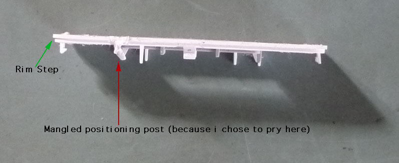
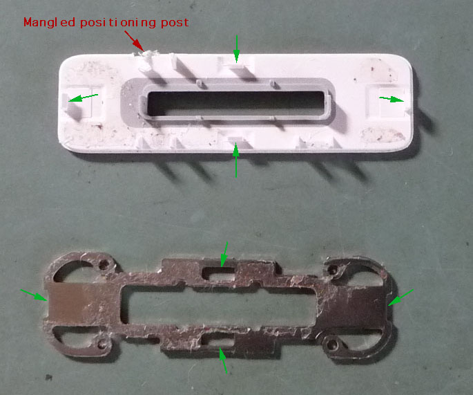
There are 4 tab catches, one at the middle of each side of the rounded rectangle: the two in the middle of the long sides are facing outward, and the two on the short sides face inward. All 4 latch onto an inner metal retaining frame, in tight contact with the back of the white plastic end piece. Unlike me, you’ll want to pry at these middle points of each side. I pried 1/3 of the way along one of the long sides, and very nicely horked up one of the vertical centering plastic posts on the back of the end piece. Again, aim for .75 to 1 mm prying penetration at this (bottom) end.
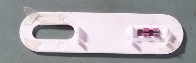
The top white plastic end piece has no inset around its circumference; it is a flat-sided piece right around 1 mm thick. It has no latching tabs, apparently instead depending wholly upon the adhesive to hold it in place. This piece may be pried up anywhere around its circumference, as long as you stick to not much beyond 1 mm in prying depth.
Cable Notes
Most of the problems related to working inside the Mini relate to damage to one or both of the flexible flat cables for the hard drive and/or the click wheel. I thought i was too sophisticated and smart to damage these, yet i very effectively damaged the hard drive cable in a nearly invisible yet absolutely noticeable-in-operation way.
The click wheel and button (control) cable connector is going to have to be unplugged from the main board—there’s no way around it. Unless you want to buy another one, be sure to very carefully pry the two mating off-white plastic connectors apart from each other. Do not pull on the flex cable/PCB material, lest you stress the solder joints between it and the connector, causing intermittent connections or outright failure.
If you find that you want or need to reconnect the control cable to the main board while the unit is disassembled, say for testing (recommended), be sure to use an excellent contact cleaner (I’m thinking DeoxIT Gold in this case) before re-plugging. This will both enhance the odds of reliable electrical connections and reduce the plugging/unplugging friction a bit. The iPod Mini will work fine with the connector plugged in and the main board out of the case… at least for basic function checks. There are 2 spring metal contact squares on the main board and one on the headphone board which touch the inside of the metal case during normal operation. The two on the main board are connected to each other and to circuit common (battery negative). The one on the headphone board does not have continuity with the two on the main board when the assembly is outside the case, so it may well be that the headphone jack will not run properly when disassembled (i did not check). The control (click wheel/button) connector does have a ground (common) connection within it, so there need not be any contact between any of these contact squares and the case for the click wheel and buttons to function. With care, the flat cable will flip/fold over to make the process of running outside the case a wee bit easier. There is little clearance between the metal case and the main PCB, so be very careful not to let the case short against any electrical contact points, such as solder joints!
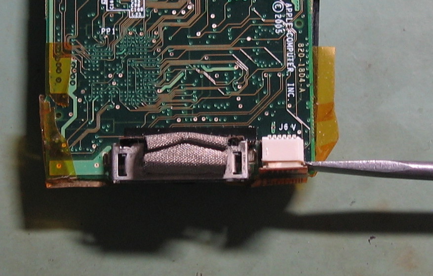
Do Not, Do Not, Do Not unplug the hard drive cable at the main board end, with the Molex® logo, unless there is no other choice. Access to the actual connector under the flat flex cable is extremely poor: the cable extends 3+ mm past the connector in all directions:
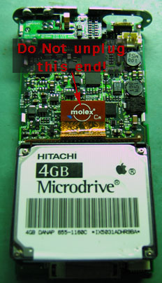
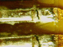
I ignored this (not knowing how critical it was) and unplugged the connector by prying between the main board and the edge of the flex cable. This very nicely fractured a number of solder joints between the flex cable and its connector, rendering the iPod stuck in Sad iPod mode no matter what was done to it:
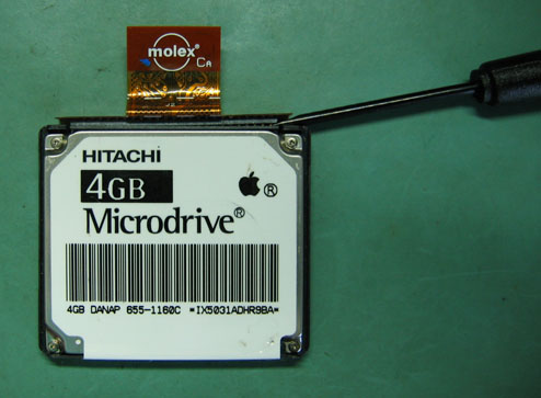
The best option is to leave the main board end attached, and unplug the drive from the drive end of the flexible cable. All the tape and blue shock absorbers will need to come off first. With something like a flat-blade screwdriver, very carefully pry the black part of the cable connector from the black body of the hard drive, as shown:
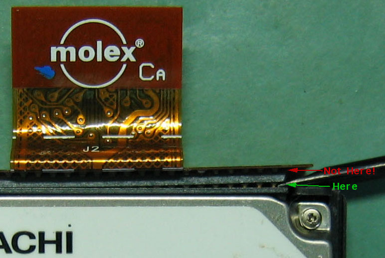
Do not pry between the surface of the flex cable material and the first black you see, which is the cable’s own connector (see the red arrow in the picture above)!
It should be very reasonably possible to do all needed work without disconnecting the hard drive cable at the main board end. If you absolutely must, first unplug the battery, then spend some quality time figuring out how you’re going to get your prying tool under the flex cable, not pressing on it, and instead prying apart the two mating black connectors hidden underneath. Good luck! When you have the cable unplugged, be sure to use your excellent contact cleaner to be sure that the contacts will be reliable and the friction reduced if you need to unplug/re-plug again. I didn’t, which is highly unusual for me. Had i done so, i might not need a new hard drive cable (or repair of the current one… we’ll see).
Battery Notes
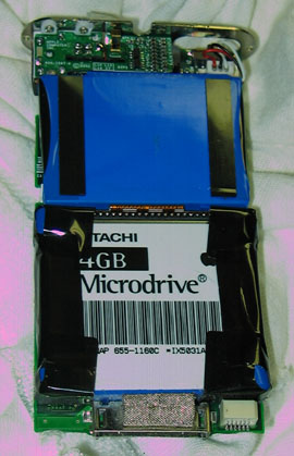
Battery replacement is pretty straightforward, once one is inside. The main precaution is to be sure that the wiring “dress” (positioning and routing) matches or is close to that of the original. It helps greatly to take a photo of the mechanism just after it is pulled out of the case and before any work is done, like this:
There have been reports of improperly positioned battery wiring having its insulation rubbed off as the mechanism is slid back into the case. This could lead to sparks, intense heating, or worse, in addition to an intermittent or inoperative Mini.
If you’re doing both of a battery replacement and the CF modification, i recommend doing one at a time, and testing before doing the other procedure. I also recommend carefully running the iPod Mini out of its case instead of reassembling then disassembling again for the next procedure.
CompactFlash Modification Notes
Again, this page is not going into the full details. The Big Picture is this: the stock miniature hard drive used in the iPod Minis uses the identical connector used by CompactFlash (CF) memory cards, long used by digital cameras. Mark Hoekstra of Geek Technique and others discovered that standard CF cards will plug into the standard connector on the iPod Mini and, once properly set up, work somewhere between decently and very well (depending in part on the particular CF card), with the expected advantages of longer battery life and vastly greater ruggedness. Probably hundreds thousands of people around the world by this point have successfully done this mod. The information on this page combined with other reading should improve the odds that you are next, and that you’ll get there with less wasted time and hassles than i had.
Capacity
In theory, since the ATA standard variant used by CF cards and the original Microdrive allows for up to 137 GB capacity, if CF cards of or near that capacity become available, they may work. No one but Apple knows if there are lower limits imposed by the firmware and software of the iPod Mini. As of October 2009, a number of people have successfully installed 32 GB CF cards. Vast numbers of people have installed CF cards between 1 GB and 16 GB capacity with success. At the low end, there have been reports of some 512 MB CF modifications that worked, yet also many reports of problems with cards under 1 GB. There are some indications that it is more likely for the smaller cards to lack full/sufficient ATA support.
Which CF Card?
This is very much the hottest topic on the very long comments areas on the original article pages, and in other iPod Mini discussion fora. In September 2009, i spent far too much time reading all these posts that i could find. What follows is a summary of all that information.
- The proposed CF card needs to follow CF specifications fully, esp. ATA compatibility.
- Where possible, choose an SLC (Single-level cell) card over an MLC (Multi-level cell) card, for longevity. Finding this specification can be between difficult and impossible. Experts (actual technicians, not customer service people) at both SanDisk and Lexar indicate that this distinction is not important for iPod use, either because the iPod won’t outlast the MLC card, or because the difference between MLC and SLC, the wear mechanism, shows up mostly in writing to the card, not reading from it. So, if you’re a typical iPod Mini user who spends a lot more time listening to your music than continually making major changes to your library on the iPod, the distinction probably does not matter. Still, for about the same price and capacity, an SLC card is likely to be more reliable and may be faster. The advantages of MLC are lower price and more easily reaching higher capacity.
- Greater success has been reported with name brands, and especially those brands who make their own memory, such as SanDisk, Lexar, and Transcend. Lesser success has been reported with brands which don’t make their own memory, especially Kingston, where what visually appears to be the same CF card and has the same part number may have different internal memory semiconductors over its production life, some of which work in the Mini, some of which do not. There have been reports of issues getting support/replacements for defective CF cards from brands whose headquarters are in China.
CF Compatibility List
compiled by Eric and possibly others, last update in message 155 of 10 July 2007. Expanded and edited by Sonic Purity, 14 Sept. 2009. Message numbers refer to comments posted to the three Geek Technique articles listed at the top of this page. When no article name is mentioned, the message is in the original article.Confirmed Working:
- A-DATA 8 GB 60x (DT, 19 December 2007, message 53 of 8 GB article)
- A-DATA 8 GB 120x (AxS, 3 April 2007, message 107 and Manu, 27 March 2007, message 95; probably also joekewl, 15 March 2007, message 80)
- A-DATA Speedy 4 GB (John B. Cole, 4 February 2008, message 222; nahoku, 28 September 2007, message 184; and Rick, 1 December 2007, message 199) John notes “the write speed is a little slow”.
- A-DATA Speedy 16 GB (wog, 12 January 2008, message 21; Nate, 13 December 2007, message 203; dromeo, 27 July 2007, message 161; Matthew Smith, 2 November 2007, message 192; and Steve, 6 December 2007, message 49 of 8 GB article [he typed 6 GB, which seems to be in error])
- A-DATA 32 GB (Randee 27 July 2009, message 333)
- A-DATA 32 GB Speedy ACF32GZ-R (Zac, 28 December 2008, message 295 and Psycho, 25 September 2008, message 278 and Nate, 13 December 2007, message 203)
- DataWrite 8 GB (Yuri, 8 June 2007, message 142)
- Hama Speed Pro 200x (Ralf, 19 December 2008, message 67 of 8 GB article)
- Kingston 45X Elite Pro (the matic, 9 March 2007, message 75)
- Kingston 133x 16 GB (Sam, 30 June 2009, message 331)
- Kingston Elite Pro 133x 16 GB CF/16GB-S2 (Ambergnat, 20 March 2009, message 321 and 808PodModder, 12 January 2009, message 308 and Tim, 10 January 2009, message 89 of 16 GB article)
- Lexar 2GB Platinum II 80x CF2GB-80-664 (stevenspmd, 2 August 2007, message 163 and Joe R, 22 August 2007, message 40 of 8 GB article)
- Lexar 8 GB Premium II 80x (bikeradam, 24 June 2008, message 60 of 8 GB article)
- Memory Corp Pro 8 GB 133x (John Valler, 10 December 2008, message 50 of 8 GB article)
- Peak 16 GB (Msky42, 3 May 2007, message 121)
- PQI 120x 16 GB (sp1t1r3, 9 November 2008, message 87 of 16 GB article)
- qMemory Xpress Turbo 150x (22 MB/sec) CF 16 GB (Maxipeg, 7 June 2008, message 258)
- Samsung blue 150x 8 GB (escalibur, 29 February 2008, message 232)
- Samsung OEM blue 150x 16 GB (mr fox, 15 March 2008, message 234)
- Samsung OEM ? (Martin Faust, 28 February 2008, message 231)
- SanDisk 512 MB (will_bc, 26 March 2007, message 94)
- SanDisk 1 MB (Jedadiah, 28 February 2007, message 38)
- SanDisk? Extreme 120x 4 GB (miguelito, 2 April 2007, message 101)
- SanDisk Extreme III (Rogh-sensi, 1 January 2009, message 298)
- SanDisk Extreme III 2 GB SDCFX3-2048-901 (Joe R, 22 August 2007, message 40 of 8 GB article)
- SanDisk Extreme III 8GB (Paco, 23 August 2007, message 169)
- SanDisk Extreme III 16 GB (Martin Daly, 25 January 2008, message 216)
- SanDisk Ultra II 1 GB SDCFH-1024-901 (Chepe Verde, 12 June 2007, message 145 and Joe R, 22 August 2007, message 40 of 8 GB article)
- SanDisk Ultra II 2 GB (joekewl, 12 March 2007, message 79 and cfcubed, 288 February 2007, message 32)
- SanDisk Ultra II 4 GB (nahoku, 28 September 2007, message 184 and atlantic.mac, 14 March 2007, message 20 of 8 GB article)
- SanDisk Ultra II 8 GB (JS, 15 August 2007, message 167; Syd, 16 March 2007, message 22 in 8 GB article; and Stephen Schoggen, 14 May 2007, message 131) JS: “Its a little bit slower to transfer the music from the computer but its faster to load the music from the Ipod.”
- SanDisk Ultra III 4 GB (Stefano, 12 March 2007, message 80)
- Transcend 1 GB (Guest, 2 March 2007, message 55)
- Transcend 4 GB 75x TS4GCF75 (nahoku, 28 September 2007, message 184)
- Transcend 2 GB 120x (Steve, 1 June 2007, message 141)
- Transcend 4 GB 133x TS4GCF133 (Hellen, 8 February 2008, message 225 and pascal, 23 January 2008, message 215)
- Transcend 8 GB 120x (Tracy K, 11 September 2007)
- Transcend 8 GB Ultra Speed 133x TS8GCF133 (Doug, 30 January 2008 and Edgardo, 24 October 2008, message 64 of 8 GB article)
- Transcend 16 GB Ultra Speed 133x TS16GCF133 (Eric, 1 February 2008; JD24, 14 November 2007, message 197; and someone else i forgot to note down) JD24 finds the transfer speed to be a bit slower.
- Transcend 32 GB (jimlat, 11 May 2009, message 326)
Suspected Not Working:
- A-DATA 120x (Steve, 1 June 2007, message 141)
- Emetec 2 GB (iMarc, 11 March 2007, message 78)
- Kingston Elite Pro 8 GB (albert, 22 March 2007, message 27 of 8 GB article)
- Lexar 512 MB (JS, 15 August 2007, message 167)
- pq1 100x (Steve, 1 June 2007, message 141)
- RiData 80x Pro II (Chepe Verde, 12 June 2007, message 145)
- Samsung 8 GB (Paco, 23 August 2007, message 169)
- SanDisk 128 MB (JS, 15 August 2007, message 167)
- Simple Tech 1 GB, STI-CF/1GB (Joe R, 22 August 2007, message 40 of 8 GB article)
- Toshiba 1 GB CF-1GTR (Joe R, 22 August 2007, message 40 of 8 GB article)
- unknown blue 150x (Paco, 23 August 2007, message 169)
- Verbatim 256 MB (JS, 15 August 2007, message 167)
- Multiple CFs under 1 GB (Joe R, 22 August 2007, message 40 of 8 GB article)
It is important to note that at least some of the cases of reports of not working may be related to problems other than the CF card, such as damage to the internal hard drive cable. If you’re working with any CF card and you cannot get past the Sad iPod, no matter what you do, if the original Microdrive® is still working, i strongly suggest you stop and plug the Microdrive back in. If the iPod Mini is working again, you may well have an incompatible or defective CF card, or need to do more setup work on it (see below). If the iPod Mini is still showing the Sad iPod even though it was working fine before it was taken apart with its existing Microdrive, odds are excellent that your hard drive cable is damaged and needs repair or replacement.
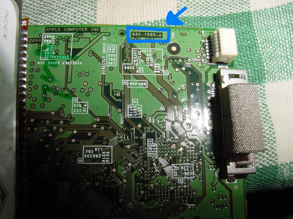
I welcome additions to the above list, or possibly links to similar, maybe better maintained lists—especially cards not already listed, and newer high-capacity cards as they come out. If you’re reporting failure, i’ll want to know that you had success with a different card and are very, very certain that the failing card is actually failing, and that there is not some other problem (like an intermittent CF cable to the main board). It will help everyone if you can provide an exact original manufacturer’s part number, complete model name, and if prominently featured, the speed rating (XYZx or actual MB/sec, whichever is easier). It may also help to know your iPod Mini model: 1G or 2G. Since you’ll have had the iPod apart anyway, look for the board revision number, in the format 820-xxxx-A, where each x is one digit:
Released by Mark under a Creative Commons CC BY-NC-SA 3.0 Deed
Known 1G numbers are 1616 and 1626. Known 2G numbers are 1648 and 1804.
Recommended CF Modification Steps for Minimal Hassles
- Be sure the Mini is updated to the current 1.4.1 firmware version before changing anything! If the Mini is currently dead, you may need to temporarily use a working Microdrive or already-working CF card to be sure that Mini is at the 1.4.1 firmware level. There have been many reports of show-stopping problems doing the CF upgrade with older Mini firmware versions.
- Format the CF card first, ideally in an external card reader. Mac OS Extended (Journaled) for Mac OS X, FAT32 for PC.
- Disable automatic sync in iTunes before doing the restore. There have been reports of problems with iTunes attempting to restore before the CF card has the needed files, with ensuing delays and problems.
- Have the click wheel connected to the iPod main board. You may need to reset the iPod or put it into disk mode.
Long-Term Results
One of the nice aspects of posting an article like this so many years after the fact is being able to report how the modification worked over time. What wound up happening is i never finished the job on my (then) True Love’s silver 2G Mini, largely because a newer flash memory-based iPod Nano then after that an iPhone came her way. Sometime vaguely around 2010 i received an entirely different pink 2G Mini, originally 6 GB. It worked, but its battery was weak. Having never finished the earlier mod, i had a sort-of new battery and 16 GB CF card all ready to go.
The card i used was the Transcend 16 GB Ultra Speed 133x TS16GCF133, which card’s packaging indicates it is MLC memory. Being much more careful this time, and with the wisdom gained from the earlier adventure, i had no problem getting the pink Mini apart, damage-free. The firmware was already at 1.4.1. I carefully replaced both the battery and the original mini hard drive with the CF memory card at the same time, doing basic functional testing out of the case. Everything worked well.
As of March 2024, the now-16 GB pink 2G iPod Mini continues to work fine. I’ve not really challenged the battery life at all, having mostly used it as an audio player in my 1981 Dodge Van with an aftermarket 1981 Blaupunkt radio cassette player to which i added an analog line level “aux” input back in the 1980s. Every once in awhile there is a minor audible glitch after a track jump or access, but most of the time doing that and all the time playing through without jumping, there have been no issues. Nor have there been issues with fast scan forward or reverse, or scroll jumping to another part of the same track. There are also newer iPods and an iPhone or two in my life which can be audio players, and still i often enjoy using the modified 16 GB iPod Mini for its comfortable feel, finger-size-reasonable click wheel, and basic no-frills black and white text display.