
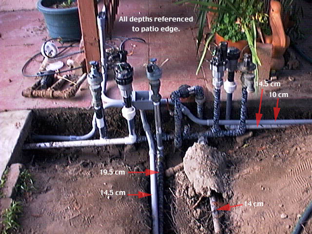
Lots going on here. Just to confuse things, the photos are looking North (towards the back of the house) and the drawing is looking South (towards the back yard).
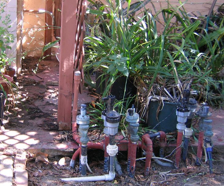
To explain all that conduit, in this and the following paragraphs we’ll reference the older time-of-installation photo (not the drawing) with white text captions and showing a bit of trench, which faces North. The conduit that curves up and onto the wood trellis (upper half of the picture, 1/3 from the left edge) heads to the house to feed the front yard valves. This run can be seen better in the later picture (showing more plant life and little to no gray conduit). This picture can be disorienting as it is looking along the face of part of the house which projects out towards the viewer for at least 1.5 meters. The conduit runs along the top of the lower trellis 2x4, curves up, then curves west and flies through the air for 1/3 m or so before penetrating a vent opening and entering the house basement. The conduit terminates just inside the basement.
As might be guessed from the lack of paint (stain, actually) on that 90° west curved piece in the later picture, this is a change: originally in 2002, the vertical rise went up just a little further and terminated in the original outdoor controller housing for the two original mechanical timers. This housing was attached to the trellis, facing into the red patio (where the majority of potted plants in the photo are now living).
Dropping down to the right is the conduit to the east (driveway) garden. Dropping down to the left and heading under the slab is the conduit to the white patio rim garden. Plunging down to the bottom of the photo is the conduit running through the center of the lawn.
In the current 2005 implementation, only the first (trellis) and last (lawn center) conduit runs are in use. The lateral runs to the gardens were intended for hooking up in-ground moisture sensors, which the existing ET controller does not use.
One of the two 7-conductor cables from the controller (in the garage) controls these backyard valves, and proceeds no further than here. The other cable passes through and continues onward to the front of the house to serve the front yard valves. All connections for both cables, except for Valve 12 (garage rose garden) are available either on the screw terminals or wire nuts in this box.
It is interesting to compare the time-of-installation trenched picture from 2002 and the later picture from 2007: no cover and no paint on the ell in the 2002 picture; squirrel chew marks in the 2007 picture. Even in the 2007 picture, there was still no paint on the curved part of the conduit between the trellis and the house. This neglected task was dealt with immediately after the photo was taken. The plants just barely visible to the left in the 2007 photo are normally filling the space between the trellis and the house (one is visible in the 2002 photo), which renders the conduit (already painted to match the trellis stain) even less visible.
That’s all for the electrical conduit story. ![]() Onward to 2005 ET Controller and Wiring…
Onward to 2005 ET Controller and Wiring…
 World O’ Appliances/Household/Plumbing/Irrigation/HVAC/Hardware
![]() The Sonically Pure Pages
The Sonically Pure Pages
This Siber-Sonically Pure Page is ![]() and
and ![]() Transitional compliant.
Transitional compliant.