Of Jesus and Sewers
The informal antenna survey
As i was saying, back in the day (oh, say May 1991… any day you want…) your intrepid D.J./Broadcast Engineer/Stereo Repair Technician set about doing an informal survey of the relative performance of a cross-section of indoor powered FM receiving antennae in relation to the T-shaped “folded dipole” (which is standard-issue with most mid-fi receivers), and that venerable reference, the rooftop antenna. The immediate motivation for the survey was the inability of a dedicated low-power FM listener and friend to get decent reception in his parents’ condemninium (sic, no rooftop receptors allowed) across the S.F. Bay in Fairfax, CA, U.S.A., a distance of, oh say, 43 km from the KALX (the desired station) tower, 3/4 high atop the Berkeley Hills.
The results surprise even this jaded techie: Can powered antennas receive weak FM signals better than yer basic plastic wire? NOOOOO! Can any indoor antenna receive weak FM signals as well as a rooftop? NOOOOO!(least not the ones i tested). Special shout-outs to The Soundwell (Berkeley, CA used stereo shoppe, 6 manufactured antennae loaned), Resistance Repair (Berkeley, CA home audio/video repair shoppe, ohsillyscope loaned), and the No Problem Household (Fairfax, CA, condemninium loaned). Here’s the Sonically Pure summary:
Antennas tested:
- 4 dipole variants (explained below)
- 6 homemade gizmos
- 7 factory indoor
- 1 factory rooftop
Most were tested in two locations: the author’s Sonically Oblique rented house in A-town (Albany CA U.S.A., 29 April 1991, clear, 22-25°C weather), representing a “city-grade” signal reeeeeal close to the KALX tower (oh, say 6km from de tower, >70 dBu-City Grade), and the No Problem condemninium in Fairfax, Hot Tub County, in fringeland, discussed above (<54 dBu).
Each antenna was tested with several different receivers: a Yamaha R300 and Marantz 2500 (both tweaked to the max, and having oscilloscope displays of signal strength, modulation, multipath, and all that other good stuff that you probably don’t care about, but that keeps me off the streets) in both locations, and additionally an old Scott 342B past its prime plus a malfunctioning (insensitive) Akai AA-R32 in Marin—possibly representative of what you use! Each antenna was adjusted for best results (no matter how impractical or ugly) and most were additionally tested in positions more representative of actual usage (crumpled up, strewn about, half-heartedly attached to the wall). Signal strength was measured (in dBf) from the oscilloscope display(s), and qualitative aural (via speakers and headphones) and visual (sillyscope) impressions were recorded for each of three representative local FM stations.
The chosen stations were: 1. KALX, Berkeley, a 500W non-commercial “alternative music”-formatted station on 90.7 MHz, using minimal audio processing[1]; 2. KYA-FM (now KYCY or who-knows-what…YEEEHAWWW!), San Francisco, a 50kW heavily-processed “oldies”-format station (back when these tests were run) at 93.3 MHz, whose San Leandro transmitter location provides extreme multipath problems at the Albany test location; 3. KDFC-FM, San Francisco, a 33kW moderately-processed commercial classical-formatted station on 102.1 MHz, difficult to receive well in many parts of the Bay Area.
Antenna Contender Profiles
Five categories of antennae were tested:
A. Dipoles
The dipoles were all variations on the T-shaped hunk of wire theme, some homemade, some manufactured. I tried three mounting positions of all dipoles: crumpled on the floor or dangling behind the receiver, held up limply (more of a “Y” than a “T”), and rigidly mounted with the top of the “T” quite straight and flat (wire not twisted). The latter is denoted as “Jesus-Mount” in this article.
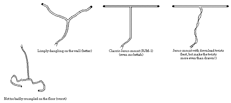
Jesus-Mounting performed substantially better than limp- or crumple-mounting in all tests (but your results may vary). Note: best reception may not occur with the antenna flat against the wall (see “T” dipole tips fo mo info).
- Antenna #1M[2] was a standard cut-for-98MHz (center of the FM band) “folded” dipole, made from unidentified clear 300 ohm twinlead. In theory, the impedance of folded dipoles such as this should be quite close to 300 ohms. The exact dimensions of this antenna have been lost (well, i had to put something in that shiny new paper shredder…).
- Antenna #2 was a manufactured dipole of the type often included with “mid-fi” receivers. It consists of 1.20m of 22 ga. clear 2 conductor “zip” cord for the feedline, split an additional 64cm (128cm or 1.28m total) forming the dipole elements. Theory says the antenna should have a characteristic impedance near 75 ohms (but what does theory know?), and should resonate (be most sensitive) near 96MHz.
- Antenna #3 was a standard cut-for-98MHz folded dipole, made from two sections of Carol 02904 300 ohm twinlead. The dipole section is 1.49m (slightly shy of the velocity factorless theoretical 1.53m, but down around 82.6MHz if the vf is .82) with a feedline length of 1.86m.
- Antenna #4 was a folded dipole of 1.655m, the theoretical ideal for 90.7MHz[3], made from unidentified brown 300 ohm twinlead, with a 3.11m feedline.
B. Freshly Homemade Goodness
The homemade gizmos were fabricated based upon inventive creations seen by stereo repair professionals, in order to test receiving antennae similar to what some of you use.
- Antenna #1A[4] consisted of a single alligator clip lead attached at one end to one of the receiver’s 300 ohm terminals, with the other end electrically unattached, clipped to a random nearby nonmetallic object chosen to hold the lead taut in a roughly horizontal orientation. This configuration was chosen to represent the category of “bits of wire” attached as an afterthought to provide some semblance of FM reception.
- Antenna #11A was a coat hanger, bent to form a triangularized loop. #11M was a length of 18ga. “lamp cord” yanked apart, split along approx. 2m (basically an instant dipole).
- Antenna #12A was a clip lead connection to the metal portion of a nearby 8' card table (“random metal object”).
- #13M represents the onset of insanity: it consisted of a long wire run to the body of a ’67 Dodge Dart (No Problem’s roofless car) parked outside the condominium. The wire was one conductor of 18ga. “lamp” cord, attached to the 75 ohm terminal.
- #14M was a similar attachment to the Fairfax City Sewer system. (Read on for surprising results).
C. Unpowered (passive) Manufactured antennae
- Antenna #5 was a B•I•C Beam Box Model 6. This is an indoor passive antenna from the 1970s with a 300 ohm built-in twinlead output, and one switch on the front for selecting best reception from one of four positions. It is intended to be placed near the receiver as another component in the audio system.
- Antenna #6 was a B•I•C Beam Box Model 10, the top-of-the line model, with both 75 ohm coax and 300 ohm screw-terminal outputs, and a tuning knob and two-position bandwidth switch in addition to the reception direction switch.
- Antenna #12M, an RCA TV-top “rabbit ears” (dual monopole) setup of unknown model number, represents friends’ favorite flea market finds. Both the VHF and UHF[5] sections have independent attached 300 ohm twinlead outputs. A multiposition rotary “loading” switch significantly affected results, with different optimum settings for each station and “rabbit ear” position.
D. Powered (active) Manufactured antennae
- #7 was a Winegard FM Stereotron amplified Model FM 4400, “looks like a rejected Klingon space ship design”, sez No Problem (basically a small dipole). The active element is rotatable, and it has a 75 ohm coax output jack and standard A.C. power cord (2.5W). The only control is a power switch.
- #8 was a Sony AN-300 Helical FM Antenna (resembles a ’50’s auto grille from your nightmares, or Grace Jones on a bad face day). This shiny silver device is yet another dipole variant, Sony-style. The element rotates with respect to the base, which houses (in addition to the circuitry) two 9V. batteries, a battery check switch and indicator, a Manual Tuning knob, and a Tuning Mode switch (Auto/Manual). Automatic tuning was tried in all configurations, and it never once worked anywhere near as well as Manual tuning (the tuning is meant to optimize the RF performance of the antenna at a given frequency).There is no power switch, as the 200µW power consumption is probably assumed not far from the self-discharge rate of the batteries.
- The Parsec LS-3 (#9) is yet another powered indoor antenna meant to be set atop the audio system. It vaguely resembles the Transamerica Pyramid crossed with the single ear of Matt Groenig’s Life in Hell rabbit. It has a wall-style A.C. adaptor, and built-in 75 ohm coaxial cable. The only adjustment is a small gain control on the front. It is intended to be run in the vertical position, but i found much better reception under certain circumstances with the unit tipped on its side. The gain control induced oscillation in the Scott receiver. It needed to be adjusted for each station.
- Antenna #10, The Terk π, resembles an overgrown petri dish displayed as fine china, or perhaps a large cosmetic case, although the illustration on its box makes it look quite like a toilet seat. It has an A.C. wall-style adapter, and a very thin coax with a standard F-59 connector on the end. There are no controls of any kind. It is meant to either lie flat (omnidirectional mode), or stand up (on the provided soft rubberish stand, similar to the stands used to hold up fine china plates for display) for directional mode. The box relates the following claims:
- Easy to install.
- Eliminates multipath distortion.
- Amplifies weak FM signals.
- Improves stereo reception and sound quality.
- Schotz Technology.
Amplifies FM strength over ten times (gain: 30 dB. noise figure 1.5 dB).
Rejects unwanted noise.
Note: i tested an older mid-1980s version, not the model one can buy today.
E. Outdoor Rooftop
Time, money, and convenience limitations precluded extensive tests in this important category. The single representative is Antenna #13A, a Channel Master 4408G, self-installed on the roof of Sonic’s one-story rental padded cell in 1986. The antenna stands approx. 2m above the roofline, controlled by a Lance LC110A rotor system. An RMS balun feeds roughly 10m of Belden 9114 Duobond II-braid 75 ohm 18 AWG premium CATV coaxial cable. All connections were treated with Cramolin® and silicone weatherproofed during installation.
Raw Datapoints
Legend:
c=clean audio
a=average (v. slight multipath o.k.)
m=moderate multipath
s=severe multipath
u=unlistenable due to multipath
w=weak, noisy
i=inaudible
v=very (modifier for any attribute)
- lowercase letters=Yamaha R300 receiver datapoints
- UPPERCASE letters=Marantz 2500 receiver datapoints
- italic letters=Scott 342 receiver datapoints
(the Akai AA-R32 has no sig. strength indication and could therefore not be plotted, but subjective impressions were included in the summary)
- multiple letters vertically indicates multipath (no single number possible)
- - indicates marked performance variations due to human movement in the room
- * indicates indoor antenna had to be positioned in an unconventional (and unattractive) position to get results this good
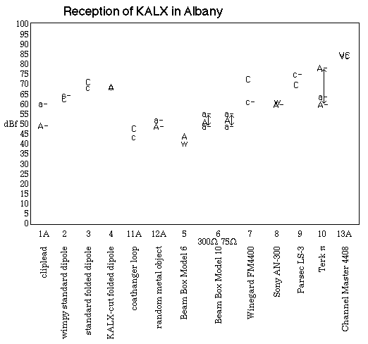
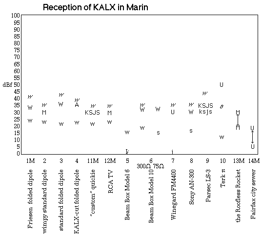
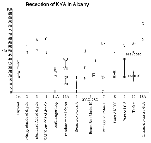
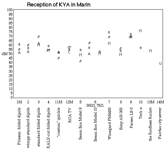
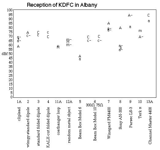
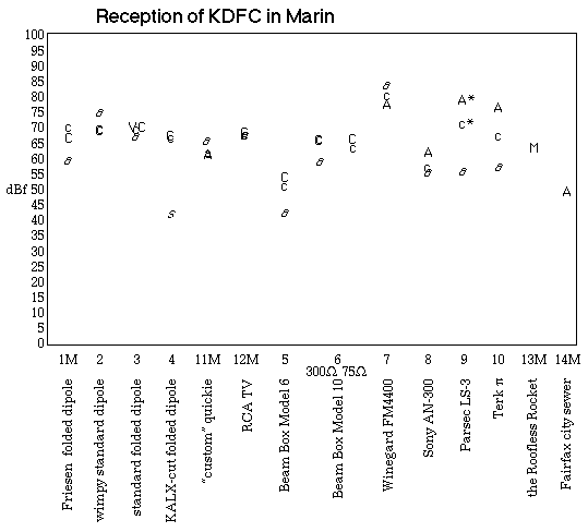
The Envelope Please…
And the winner is……THE ROOFTOP ANTENNA!!, which obliterated all other contenders—nothing else was even close for cleanest, quietest signals for all three stations on both receivers. The message is clear: if you care at all about FM sound quality, settle for nothing less than a rooftop (if’n you can).
But what if you can’t put up a rooftop receptor? The indoor winner was THE 300 OHM FOLDED DIPOLE! (Jesus-Mount), which tied or beat all 7 factory indoor antennae. Ya haveta make sure it is truly a folded dipole and install it correctly, but at least you’re not wasting money on pretty but unproductive factory goods!
The best of the homemade fabrications was the coat hanger loop, which could not approach a good dipole but joined several other bargain-basement self-made creations in tieing most factory antennae, and all of these worked better than the Beam Box Model 6, including the Fairfax City Sewer! Most of the homemade antennae, and all the powered antennae, were fairly sensitive to human bodies roaming about (the rabbit ears and the better dipoles suffered least from motion in the ether ocean).
The clear loser was the Model 6 Beam Box. The Parsec refused to pull in KALX in Fairfax: it switched to KSJS whenever it was plugged into power! (KSJS has since moved to 90.5 MHz, so this wouldn’t happen today).
Some readers may be heartened to hear that the powered antennae provided a classic demonstration of the deceptive nature of relying on limited measured specifications to correlate with perceived sound quality. Looking back at the claims made on the Terk π box, the amplification of weak signals cannot be denied, but unfortunately, noise & distortion are amplified proportionally as well (for all powered antennae tested, not just the Terk). Sure, the signal strength meter reads nice & high, but in many cases the audible sound quality was inferior to one or more lower-reading passive designs (usually dipole variants). The remaining claims played out as follows:
Tested True
- Easy to install.
- Amplifies weak FM signals.
- Schotz Technology.
Tested False
- Eliminates multipath distortion. [sometimes clearly increases it, seemingly due to poor cable shielding]
- Improves stereo reception and sound quality.
Amplifies FM strength over ten times (gain: 30 dB. noise figure 1.5 dB). [gain wasn’t even close]
Rejects unwanted noise.
Similar critiques apply to all the powered antennae.
[1]KALX used/uses? an Orban Optimod® 8100A, set near Orban’s suggested “audiophile” minimal-alteration settings.return
[2]M=tested in Marin only.return
[3]if one lives in fairyland, where the velocity of propagation is unity. Assuming a velocity factor of .82 for twinlead, the actual active length should have been 1.36m. It would be kind of you not to ask who made this antenna….return
[4]A=tested in Albany only.return
[5]The UHF results were sufficiently disappointing to not be included in these tests. Only the VHF section was fully tested.return
