- Breville 800 Repair Home
- Normal Sequence of Operations
- Disassembly
- Electrical/Electronic Issues
- Mechanical/Water/Hydraulic Issues
- Modifications
Disassembly
The 800ESXL may not be the easiest device to get into, yet it is not too bad when one knows the tricks. My technique deviates slightly from some notes found online, yet i find it works out well for me. Naturally, the unit should be unplugged and have all its trays, water tank, and whatnot removed before commencing.
Index
of topics covered on this page- Quick Note on Reassembly, for Easier Future Disassembly
- Lower Rear Panel
- Left Interior Side Panel
- Top Cover
- Circuit Board Box
- Selector Control Knob
- Power Button Assembly
Quick Note on Reassembly, for Easier Future Disassembly
Site correspondent and coffee lover Chris Robinson submitted an idea compelling enough that i want everyone to see it, hence it’s up here at the page top:
Just a note on screws/threading also: The side panels are made of cast alloy that can suffer from corrosion in the screw sockets if moisture is present. Those not familiar with appliance repairs may not know enough to re-assemble those screws that go into the alloy with a very tiny bit of grease to prevent them seizing in place in the future. I used a food grade lanolin based grease. It’s also very useful to do this for the screw in the brew head that holds the screen and silicon pressure gasket in. That can be a devil to get out even on a fairly new unit because of its awkward location.I very much wish that this had occurred to me when the machine here was new. At this point, the brew head screen screw is not possible to remove without drilling out the screw. (The best penetrating lubricant i know—Kroil—has failed.) Chris’s advice is highly recommended!
Lower Rear Panel
This is the step not usually found elsewhere: while not essential, i found it makes removing and replacing the side panel easier (though still not truly easy).
Remove the two screws on the bottom rear and pull the panel down just enough to clear the two positioning pegs not far from the two screws just removed:
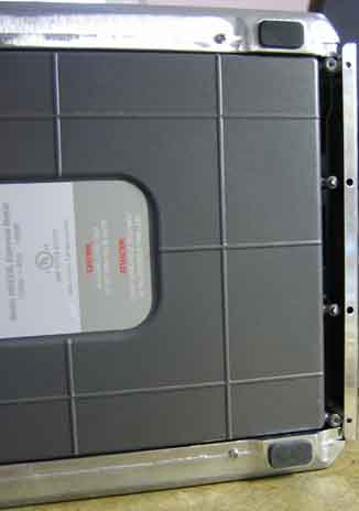
The top of this panel is held in place by two offset tabs: push the panel up a bit, do some wiggling, and experiment with the rear water loading tray in various positions. Eventually the panel will come free.
Left Interior Side Panel
This needs to come off to access one of the screws holding the main circuit board protective box. Remove the 4 visible screws holding the left (when viewed from the front of the machine) interior plastic side panel in place. The panel will be happy to come off at the bottom, yet will hang at the top. The hangup points are the two mounting studs for the top screws plus the interlocked plastic piece above. If one pretends that interlocking area is a hinge and does some judicious wiggling, it is possible (though not easy) to get this piece out and back in unbroken. Expect scratches. If this bothers you, you’re on your own loosening the left exterior metal chassis part to discover if that makes this process any easier.
Actually, it apparently bothered correspondent and hot beverage lover Ian L., who shares with us the following:
The plastic casing covering the power cord & circuit board case can be removed fairly easily without bending it. The advantage is avoiding snapping those ill-fitting screw guides or scratching the plastic piece up. To remove it, you must first remove the warming plate and unscrew the two screws holding the left metal casing. Then the plastic casing can easily be taken in or out of place. I discovered this because I had to remove the front plate with the buttons to get to the button circuit boards.
Site correspondent and hot beverage lover Trev notes:
I found it easier to loosen the whole side panel completely (2 screws at the top and 2 screws at the bottom) in order to remove this plastic panel. Behind this plastic panel is the lower screw for the circuit board casing, so the plastic panel needs to come off.
Then there’s the method of site correspondent and hot beverage lover Matthew L.:
Getting inner left plastic off without scratches: remove two screws from plastic cover under pump which then flexes enough to allow easy gentle removal.
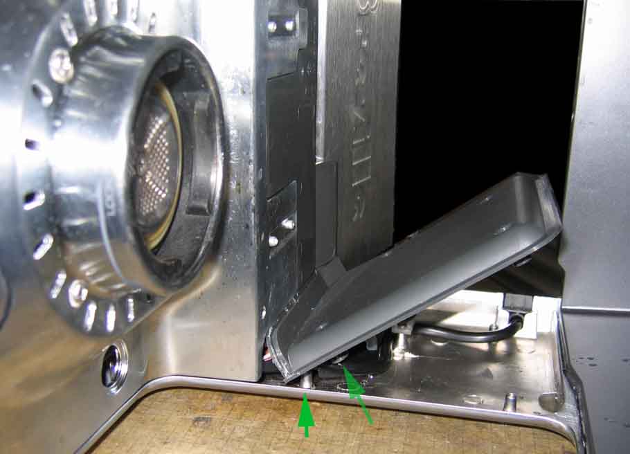
The green arrows show the part of the cover panel and its mating stud, clearly out of alignment as shown here.
In March 2024 i had need to once again remove this cover. First i tried Matthew L.’s pump area plastic cover screw removal allowing flex method, but didn’t have the technique down else wasn’t patient enough. Next i tried Ian L.’s suggestion to remove the two top screws holding the left side panel. This worked easily and well for me. Any of these three options is going to be better than my original force-and-scratch method, though even that one does work. Use whichever method works for you!
Top Cover
This one’s a very tight fit: the sides of the unit press inward onto the top cover piece.
Look at the inside top of the unit, where the water comes out. Locate two gray cones, one on each side. Each has a #2 Philips head screw about 6 cm from the visible cone entrance: remove these, both the screws and the cones.
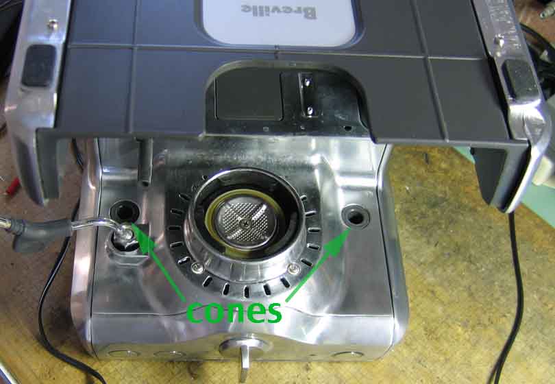
Restore the unit to normal upright orientation if necessary. Besides the screws, the top cover is held in place by beefy metal locking tabs along each side:
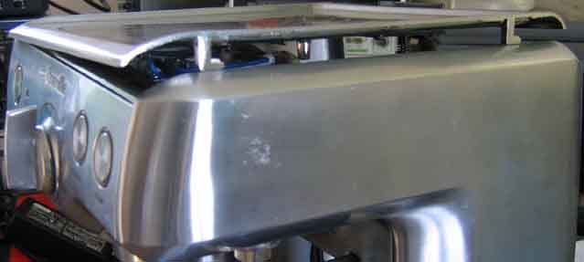
Open the rear water loading tray and push (actually, whack) the top cover horizontally towards the front of the unit a minimum of 7 mm (1 cm should be plenty). The cover should now lift off, restrained only by the grounding wire, which will need to be unscrewed to allow complete removal.
Circuit Board Box
- Remove the two screws, one above and one below, holding the box to the chassis left side.
- Carefully document the wiring. No picture here because Breville did not see fit to use a sufficiently diverse array of colors for a proper color code (likely would drive up the price of these: high-temperature wire insulation), so you’ll need to make your own, or apply paper labels or other markings (and remove them once the work is complete, before reassembling and using the unit, unless they can withstand the normal operating temperature safely, for an indefinitely long time).
- Once marked, unplug the connectors as needed.
- For greater freedom of access, unscrew the two screws holding the water tank LED to the chassis.
There is one remaining two-wire cable which does not unplug and is not easily freed, other than perhaps by cutting one or more wire ties. This cable goes to the microswitch (one of two) on the Selector Control: the knob controlling the choice of water outlet (this switch is closed when the main water/filter output is selected). I chose to just deal with it, as with everything else disconnected there is sufficient freedom for the work i needed to do.
Selector Control Knob
It is not necessary to remove this knob for doing the most common electrical repairs, though it may be necessary for boiler unit and other work. I did attempt to remove the knob at one point during my initial repairs, but lacked the cajones to carry through to completion: it didn’t want to budge. Thanks to several correspondents, we all now know the story: there’s a locking tab on the knob. With the knob in its neutral (vertical) position, the tab is facing the Power button/circuit board side of the machine:
The tab, made of the same black plastic as the square shaft assembly, looks “fuzzy” in my photo because i chewed it up a bit whilst working to press it in sufficiently. Here’s a photo from site correspondent Paul, with the pieces partially disassembled, which much more clearly shows the latch tab:
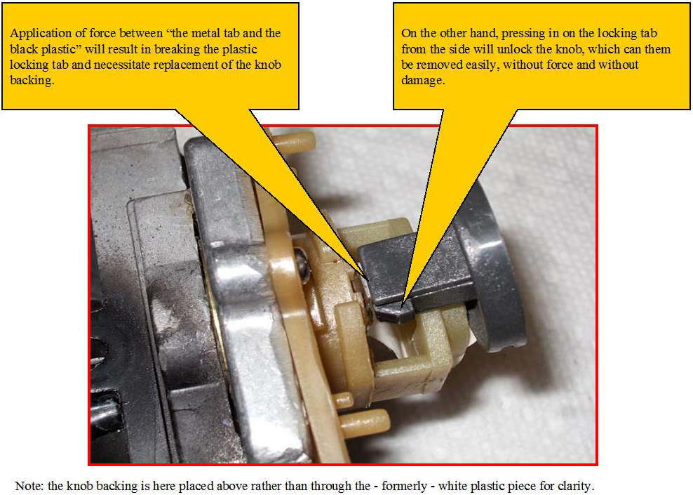
In February 2012, i tried Paul’s method on the unit here: no matter what i did nor what tools i used to press in the locking tab, never once could the knob “be removed easily, without force”. I sure enough got it out without damage, but i had to both push in the locking tab AND at the same time pry out the knob, using this prying method:
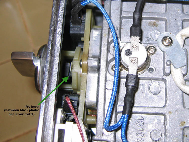
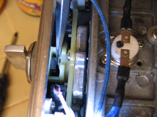
So… YMMV. Just know that there is a locking tab, and if it isn’t released, part of the knob assembly may break, resulting in cost and/or hassle to mend things. By all means, try to pull the knob out by simply pressing in towards the center of the shaft on the locking tab to unlock it whilst pulling out the knob. But if that fails, pry with care while the locking tab is held in release position.
Power Button Assembly
Site correspondent NL Foust shares this successful technique:
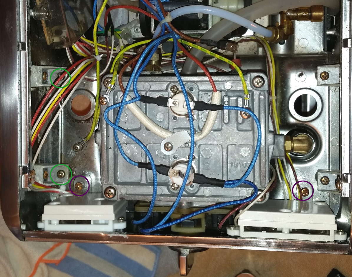
I pulled the selector knob. Then remove both front panel screws (in purple circles in photo). Remove both upper side panel screws on the left side (in green circles in photo). This allows enough room to lean the front plate forward on the left side to gain access to the power button assembly mounting screws.
Have any Breville 800ESXL repair tips? Send ’em in! I’ll endeavor to add the seemingly good ones to these pages, at my usual glacial pace. (Please let me know if you want to be credited or remain anonymous. Thanks!)
