Breville 800 Series Service Manual, Circuit Comparisons, Production Changes
Index
of topics covered on this pageService Manual PDF + My Schematic
- Service Manual PDF: Information and Downloading
- Revision History of my hand-drawn schematic
- Schematic/Wiring Diagram Comparisons: Breville PDF and Sonic’s hand-drawn
Service Manual PDF
In the summer of 2011, a kind reader provided me (and us all) with what appears to be the service manual for the Breville 800 series of machines, as of early 2008. The document explicitly lists the model 800ES for Australia and New Zealand, the 800ESXL for the United States, and the BRE800ESXL for Canada. There are also various notes for the “A” suffix models, which do indeed appear to be “new and improved” revisions.
Please Please Please download the following PDF file rather than repeatedly viewing it from this site (if your device supports downloading)! (This should happen automatically in most cases as long as you/your device and software are not doing anything to override forced downloads.) This will help keep my WWW hosting costs low, allowing me to keep this site free and ad-free and donation request free. Thank you!
Breville 800 class Service Manual PDF (PDF download)I present the PDF file here for the benefit of Breville 800 series machine owners wishing to keep their own machines useful and running. Neither myself nor the person who provided it to me can find any copyright information on the PDF file. I do not intend to violate Breville’s copyright, and if contacted by the company and asked to remove the PDF, i will. I do hope that Breville will choose to allow the file to remain available for all our benefit, and especially to help keep as many of these machines as possible running well.
Had this been available to me when i first needed to work on our own machine here, it is unlikely that i would have gone to the time and trouble to draw out my own schematic. Comparing the two, there are some interesting differences. Open up the PDF in another window to the schematic (p. 6) and let’s compare it with my schematic, repeated here:

Revision History of my hand-drawn schematic
Before we get into comparisons, some notes on the revisions (to date) of my schematic:
- Rev. 1 (initial release), 22 December 2009
- GIF file format, for maximum compatibility with WWW browsers of the era. Missing details on Steam/Hot Water circuit board.
- Rev. 2, 10 August 2013
- Added R14 and R15 470Ω each Steam and Hot Water LED series resistors. Added C9 and C10, but not their capacitances
- Rev. 3, 25 March 2024
- The wiring around the Power switch and related LEDs/resistors was significantly incorrect on earlier revisions (appreciation to James L. for finding the error and alerting me). Carefully reviewed the wiring of the actual machine here, which matches what James L. sent, as well as better fitting the Breville service manual wiring diagram’s wiring.
- Redrew schematic as a Scalable Vector Graphic (SVG) file, which will hopefully be sharper and clearer and scale better on various screen types and sizes
- Added missing main board C8 across Power button contacts. Interestingly, there is a duplicate unstuffed C8 in electrically the same position over on the Power button/light P.C.B.
- Added capacitances for C9 and C10
- Redid coloring to hopefully make colored wires easier to see, and better differentiate between parts on the main P.C.B. and parts off of it
- Rev. 4, 24 November 2025
- Somehow over all these years i managed to omit the thermal fuse sitting atop the thermal block, in line with the Line power wire. Looks to be red from the power cord to the thermal fuse, then brown from the thermal fuse to the L terminal of the P.C.B. Have never removed the thermal fuse here, so no idea of its rating(s).
- Temperature ratings of thermostats added, per Breville service manual.
- Pump wires made a little more obviously red. Honestly, to my (assumed normal) color vision, the red and brown wires in this machine are very close in color.
- At some point, the circuit common connection for S1 disappeared. It is back.
Schematic/Wiring Diagram Comparisons
This section significantly revised November-December 2025
In late November 2025, via correspondence with another Breville 800ESXL owner, i realized my original analysis of the circuit in the PDF service manual which was on this page from its start in October 2011 through late November 2025 was seriously flawed. This section has been significantly revised with updated, correct (or closer) information.
I had considered making an Errata page, but concluded it would create more confusion and unintentional misinformation. If for some reason you need to compare or refer to the material which used to be here, please use this Internet Archive Wayback Machine link.
At first, this looks like an entirely different circuit. Yet after careful study, it is mostly the same circuit, drawn differently. The Breville service manual covers both 120V North American and 230-240V Australian (domestic) and New Zealand models with one schematic diagram, with no notation on the schematic regarding whether the circuit applies to only one or both of these voltage levels. Given the date of the PDF as 19 February 2008 and the date code on the machine here from 2006, i brashly/rashly ASSumed that…
- The schematic in the service manual reflected a newer design
- Power supply component differences were due to 240V/120V differences
Looking more closely at the illustrations in the PDF, the main circuit board has the same TSK-1835A designation as the machine here, but the date code in the PDF is 04/04/28 (28 April 2004) whereas the one here is 05/02/21 (21 February 2005). So even though the PDF is newer, the illustration of the circuit board is not, and the schematic age/revision is unknown.
Comparison
Unknown whether production changes or documentation errors unless specifically noted. If production changes, unclear which is newer, and there are other undocumented changes not covered here.
Variations
| Item | My Schematic and actual machine here | Breville PDF | Comments |
|---|---|---|---|
| SCR Q1 | 2P4M 400V | 2P6M 600V | |
| C1 | 1.5µF | 0.33µF | V++ |
| R1A & B | 120kΩ | 56kΩ | V++ bleeder resistors. Two in series for voltage-withstanding reasons. |
| R2 | 47Ω | 100Ω | V++ |
| R23/24 | R24 1.5kΩ 2W | R23 1.2kΩ 1W | V+ 5VDC supply |
| R6 | 4.7kΩ | 3.3kΩ | SCR gate drive series resistor |
| R8 & R9 | 4.7kΩ | R8 twice 3.3kΩ | |
| MOV V1 | exists | missing from schematic, but exists on photograph | Surge-suppressing varistor. Schematic omission likely an error. |
| D8 | Internal to pump, not on schematic | External, across thermal fuse too | |
| C8-10 | exist | missing | 10 nF contact de-bounce capacitors each in parallel with one of the Power, Hot Water, and Steam buttons |
| RL1 contacts switch | low (Line) | high (Neutral) | side of powerline—Major Change! |
Swaps
| Item | My Schematic and actual machine here | Breville PDF | Comments |
|---|---|---|---|
| C2 | 100µF 50V | 220µF 16V | Error in PDF: 24 to 27V at this point in the circuit |
| C4 | 220µF 25V | 100µF 16V | C2 and C4 values swapped |
| Q2 emitter LED | Tank Illuminator | Power | electrical position of Tank Illuminator (water level) and Power LEDs swapped |
| LED driven off P50/P61 | Power | Tank Illuminator | P50 drives the base of Q2 |
| P50 | Q2 base drive | T/F sense line | See comment below |
| P61 | T/F sense line | Q2 base drive | See comment below |
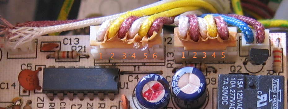
Carefully rechecked in late March 2024, and absolutely for sure IC pin 1 (P50) goes to R13 and pin 3 of the 5-contact plug leading to the power button P.C.B. on the unit here.
Production Changes
The Breville model 800 (ES, ESXL, etc.) espresso machine went through a number of production changes over the course of manufacture—this we know, from many reports and photos from site correspondents showing the changes, along with discrepancies within the PDF service manual vs. known production machines. If there exists documentation on production changes, it is internal to Breville Group Limited, so this section is composed of inferences, guesses, and occasional known data points. The focus here is primarily on electrical/electronic production changes, as that seems to be the area which trips most people up when trying to maintain and repair these machines.
V++ Power Supply
The majority of most obvious changes i’ve encountered from site correspondent reports plus comparing the PDF service manual to my own schematic drawn from the September 2006-manufactured machine here are in the main 24 or 27VDC power supply, which i label V++. Often several related parts changed at the same time, making it difficult to get a sense of the changes in a list or table format. Therefore i present schematic fragments from my hand-drawn schematic for each known variant, with the parts values which have changed shown for each iteration, along with any known production date information.


All of these are minor variations on the common capacitive power supply (Wikipedia). This type of power supply uses reactance to lower the power (lowers voltage and limits current), typically for conversion to low power D.C. for operating electronic circuits, such as the Breville 800’s circuitry. Below are details on each known variant.
Prototype
This is the version photographed in the 19 February 2008-dated Breville 800 Class Espresso Machine service manual PDF. It looks unlike any other board i’ve yet seen in photos or the one here in person. The fact that the IC is socketed—expensive!—further suggests this was a pre-production board. Part values determined by inspecting the photograph in the PDF, which is why some could not be read and are marked as ? or “looks like”. Note that many part values do not match the schematic in this very same PDF service manual, when in theory they should be identical.
There is no indication whether this board was meant for 240V or 120V house power, or both. Not knowing C1’s value, it is not possible to calculate maximum theoretical current for any powerline voltage or frequency. The 220Ω value for R2 is much larger than production models.
Initial Version (maybe?)
This version of the circuit has never been seen by me in physical form—only on the schematic in the Breville service manual PDF. I don’t know whether this actual circuit was used in early production machines, very late (circa 2008) production machines, or no production machines.
The omission of MOV V1 across the powerline (L and N terminals) is likely an error: of the dozens of board pictures i’ve seen plus the actual board here, not one of them omits this part. Similarly labeling the 1.2kΩ dropping resistor R23 rather than R24 as marked on all boards i’ve seen is likely a documentation error.
C1 at 0.33µF is lower, and R2 at 100Ω is higher, than on any boards for any voltage i’ve seen. Each of these choices lowers the available power. Again we don‘t know whether this is a 240V 50 Hz circuit, 120V 60 Hz, or supposed to work for both. Here’s what in theory this circuit can put out:
| Revision | C1 Reactance | C1 + R2 Impedance | Max. Current |
|---|---|---|---|
| Rev. 0 120V 60Hz | 8kΩ | 8.1kΩ | 15mA |
| Rev. 0 240V 50Hz | 9.6kΩ | 9.7kΩ | 25mA |
Required Current?
To know whether any of these circuits can supply enough power, we need at least a rough ballpark estimate of the total current draw of the electronics of these machines.
On the V+ 5VDC circuit, we have R24 1.2kΩ dropping 24V - 5V = 19V, limiting current to ≈ 16mA. Typical draws for the LEDs are 8mA for Power and Hot Water or Steam ring LEDs + 7mA for Heat LED, leaving maybe 1mA for IC U1 and regulator ZD1. Seems plausible, so i’ll just use 16mA for this whole branch.
Because it will be relevant later on, i’ll note here that for 27V 1.5kΩ models R24 can supply ≈ 15mA total for the V+ circuit.
Back to this 24V circuit variant, we add 15mA for RL1 + 13mA for ZD6, for 16mA + 15mA + 13mA = 44mA—far more than this circuit can produce at either line voltage/frequency. Sooo… something’s off here. The ZD6 value was for a later model, so maybe it draws less here? Or maybe this exact circuit never made it to production but wound up in the service manual anyway. Let’s move on to analyze circuits which have actually been seen in the real world to find out if they can get close to supplying 43 to 44mA or more.
Revision 1
This is the earliest production board whose photo i have actually seen. Circuit board has been updated from the prototype, and is dated 04/08/27, or 27 August 2004. C1 has been more than doubled to 0.82µF and R2 dropped all the way down to 22Ω (a rounding error when we roughly calculate total series impedance below). R1A and R1B aren’t known because they’re under C1 on the board, and were not visible in the photo sent to me. Thankfully their values are immaterial for the rough calculations we’re doing. This 240V/50Hz machine is the first appearance (i’ve seen) of 27V 3W for ZD6, so we’re looking to meet or exceed 43mA total current supply. Let’s find out…
| Revision | C1 Reactance | C1 + R2 Impedance | Max. Current |
|---|---|---|---|
| Rev. 1 240V 50Hz | 3.9kΩ | 3.9kΩ | 62mA |
Now that’s more like it! This circuit can absolutely supply enough current… assuming nominal line voltage and all components spot on in value. What if the mains is running 10% low? For 240V nominal that would be 216V. 216V ÷ 3.9kΩ = 55mA, so we’re still good. Let’s guess that C1 has a tolerance of ±10%, and pretend it’s 10% low: 0.80µF. In that case its reactance calculates out to be roughly 4kΩ. That’s close enough that i’ll only look at the extreme case of 10% low mains + 10% low C1: 216V ÷ 4kΩ = 54mA. What if the mains is 230V? 10% low there is 207V. 207V ÷ 4kΩ = 51mA (lots of rounding going on here), which still has a margin of safety over the 43mA we know the machine needs.
What happens with C1 when it fails is more extreme. Site correspondent Jade’s 240V Australian (domestic) machine had C1 labeled as 0.89µF—slightly higher than our current circuit under analysis. Jade’s actual measurement was 0.35µF—roughly 60% low! We know from roughly calculating required current above that capacitance this low cannot supply enough current for the Breville 800 espresso machine to work. Sure enough, when Jade replaced C1 with the rated value, coffee be brewin’ again!
Revision 2
At least 5 site correspondents so far have sent in photos of this/these variation(s), two of them possible to date from either a date code on the IC (2005 August) or on the machine itself (2006 June). All have been 120V machines manufactured for Canada or the U.S.
C1 is increased significantly, to 2.2µF, with R2 basically doubled to 47Ω. The capacitances of C2 and C4 have swapped, with the voltage ratings remaining where they had been. Guessing that Breville found that the V+ 5V microprocessor supply needed more filtering than the V++ supply. Earlier machines in this revision series, such as the 2005 August date-coded example, continue to have ZD6 as 24V 1W as in at least some of the prior revisions… maybe the 120V prior revisions? Later production (e.g. the 2006 June example) switched to 27V 3W for ZD6, as for the Rev. 1 240V example. R1A & R1B are 120kΩ—closer to the prototype photo values. What can these variants put out for current?
| Revision | C1 Reactance | C1 + R2 Impedance | Max. Current |
|---|---|---|---|
| Rev. 2 120V 60Hz | 1.2kΩ | 1.2kΩ | 100mA |
Yowza! 100mA should be plenty of current for running all the circuitry with low tolerances and line voltage and then some! Maybe there had been enough issues in prior production with C1 losing capacitance that Breville thought they needed this extra margin.
And yet, this revision still has V++ power supply issues, often C1. Only some of the 5 boards of this revision have had V++ problems, so maybe Breville was onto something.
Revision 3
I used to think the machine here was older production, given the 2008 date of the Breville PDF service manual. Upon closer, more careful inspection, so far it—Rev. 3—is the newest board revision i’ve seen. 3 boards like this have been seen to date, including the one in the one-and-only actual machine i’ve had my hands on here in this household. That machine has the 2006 September date code—only one month after the newest known Rev. 2 board (discussed above). Another machine with this revision has a 2008 early September date code, possibly suggesting that this was a final or near-final revision… at least for the 120V 60Hz machines.
For Rev. 3, C1’s value drops back to 1.5µF. R24 sees its first-ever change: increased from 1.2kΩ 1W to 1.5kΩ 2W—the 1mA lower current limit for the V+ branch of the circuitry. Otherwise the circuit is identical to late Rev. 2, with ZD6 at 27V 3W. Why would they drop the capacitance? Let’s look at the numbers:
| Revision | C1 Reactance | C1 + R2 Impedance | Max. Current |
|---|---|---|---|
| Rev. 3 120V 60Hz | 1.8kΩ | 1.8kΩ | 67mA |
Was there a problem with having so much available current in Rev. 2? Was the cost of the larger capacitor for C1 a problem? Or maybe its size/mass? No idea. I do know that per the rough calculations, 67mA of available current ought to be a sufficient margin without being excessive.
None of these Revisions Match My Board! Now What?
Congratulations! You likely have a revision not (yet?) documented in this article. If you’re quite sure your board does not match any of these variants, for the benefit of the Breville repair community it would be kind of you to email me with the following information:
- A good, clear photograph of the entirety of the component side of your machine’s printed circuit board
- One or more additional photographs showing the sides of C2, C4, R2, and R1A/R1B and C1 if any of their values are not visible in your main photo
- A photo of the label on the bottom of your machine which shows the entire label and clearly shows the date code
A good photo of the main board is required for me to verify a new/different revision. If you are able to correctly interpret parts values, you are welcome to supply that information as text to me rather than additional photos. Similarly if you will accurately supply the power line (mains) voltage and frequency and the date code on the bottom label as text, no photo is required for that. In some cases, i may contact you for additional information. Thanks!
Older Revision V++: Modify? Or Fix?
Let’s compare and contrast the pertinent findings:
| Revision | C1 Value | C1 Reactance | C1 + R2 Impedance | Max. Current | Sufficient Current? |
|---|---|---|---|---|---|
| Rev. 0 120V 60Hz | 0.33µF | 8kΩ | 8.1kΩ | 15mA | No |
| Rev. 0 240V 50Hz | 9.6kΩ | 9.7kΩ | 25mA | No | |
| Rev. 1 240V 50Hz | 0.82µF | 3.9kΩ | 3.9kΩ | 62mA | Yes |
| Rev. 2 120V 60Hz | 2.2µF | 1.2kΩ | 1.2kΩ | 100mA | Yes |
| Rev. 3 120V 60Hz | 1.5µF | 1.8kΩ | 1.8kΩ | 67mA | Yes |
As long as C1 in your machine is rated 0.82µF or higher, whatever circuit your machine has might as well be repaired.
Modding for Non-Electronic Experts
If you choose to modify, to follow Breville’s design engineering, you will need to replace all components whose values in on your existing board differ from what’s marked on the schematic fragment for the revision to which you’re altering your circuit. In other words, if you have a 120V 60Hz machine with a Rev. 2 board and you want to change it to Rev. 3, you will not only need to change C1 from 2.2µF to 1.5µF, but also R24 to 1.5kΩ 2W and if ZD6 is not already 27V 3W (or higher wattage), make that change too.
Is it absolutely required to change all parts for a mod? No… but if you’re unsure what you’re doing, it’s safer to make it match what Breville did. If you know more than that, the next section applies to you, not this one.
Modding for Electronic Experts
You’re still reading? Hi there! Of course you can make partial component changes that don’t match any of the schematic fragments, pick values not used in any of the known Breville revs, or design an entirely different power supply circuit that supplies the (apparently very approximate) needed 24 to 27VDC @ >44mA with whatever current safety margin above that for low line + low component tolerance you like.
If you’ve designed, tested, and used for some months a particular design you’d like to share here, let me know.
IC: No Known Changes
Over the years, several site correspondents have carefully informed me that their board has an IC marked “1835BSAA”, with the letters capitalized or lower case. Often it’s a white sticker attached to the IC. These stickers often fall off, leading to what can appear to be an unmarked IC. I have vague memories from nearly 2 decades ago of the sticker on the machine here falling off, else my removing it, to get to the IC printing from the manufacturer underneath.
In any case, there is no other known IC revision than 1835bsaa in any production Breville 800/ES/ESXL espresso machine to the best of my knowledge as of the revision date of this page. No need to supply that information unless it differs or your board has some other variant not yet documented here.
Return to where you were in the main Electrical/Electronic Issues - Breville 800ESXL Repair article