Hitachi SERA486-07 Throttle Position Sensor Internal Contact Cleaning
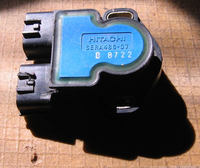
Back in 2011, my good friend Aaron’s Nissan Frontier pickup truck was having driveability issues, including moments of spontaneous engine acceleration and other weirdness. Research and troubleshooting soon enough led us to the throttle position sensor (TPS). On his truck the part was OEMed by Hitachi, their part number SERA486-07 (as seen in the photo of the back of the unit above).
Being an electrical engineer/electronics person with many decades of dealing with issues related to dirty or otherwise poor electrical contact connections, and learning that this older design TPS was what the Wikipedia article on Throttle Position Sensors calls a “potentiometric design”—in other words, a variable resistor with metal contacts wiping across a resistive element—my instinct was to save my friend some money and clean the contacts with my favorite contact cleaner.
Sealed Deal
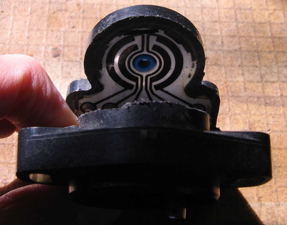
Problem was, the unit was totally sealed up. This is actually a Very Good Thing under normal conditions, in terms of keeping dirt, corrosive vapors, and so on which are mainstays of the automotive under-hood environment from getting to the contacts. It’s necessary to seal TPSes well, and Hitachi did an excellent job. Even attempting going in from the front:
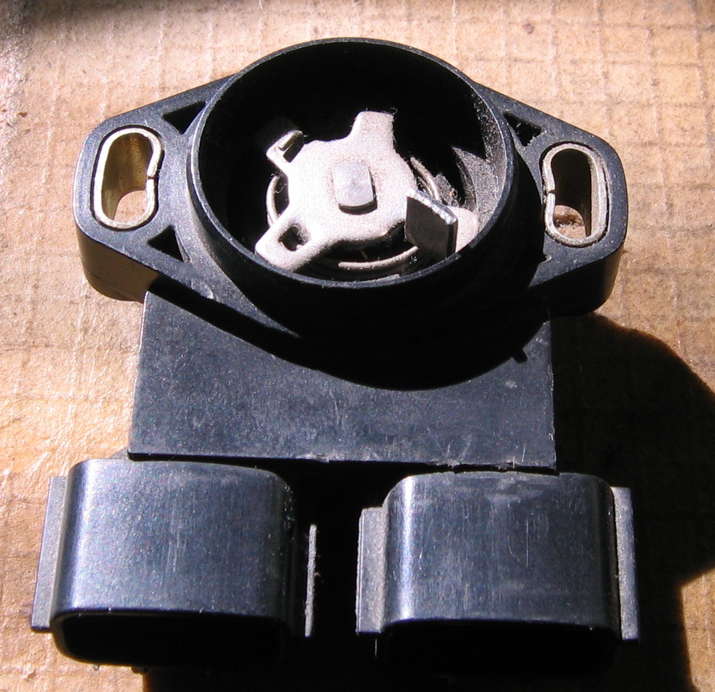
there was not even a tiny point of entry for any cleaning chemicals. This makes sense, since the front with the actuator is (or at least can be) exposed to fuel vapors and whatnot flowing through the throttle body.
The bottom line was that the only option which made sense back in 2011 with job/time pressures was replacing the TPS, which is what most people do. My friend bought a new part, we installed it together, and the weirdnesses were resolved.
Getting In
I knew there was probably some way to drill a hole at a strategic location on the TPS, inject spray-format cleaning chemicals, then seal the hole back up. The question: drill where?
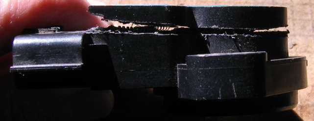
With the old TPS officially declared dead and of no use, eventually (years later), i got around to carefully sawing it open around its side edge (destroying it), to be able to figure out where one could drill a hole for contact cleaner injection without destroying a still-intact TPS. Needless to say i can’t test the theory on this particular TPS because to gain the knowledge i had to trash it. Hopefully what i have learned will help you clean yours without trashing yours.
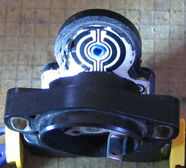
Let’s take a look at the normally-sealed electrical insides of this device, and orient ourselves. Pulling the sawed-apart back upward, we first look at the moving contacts attached to the actuator:
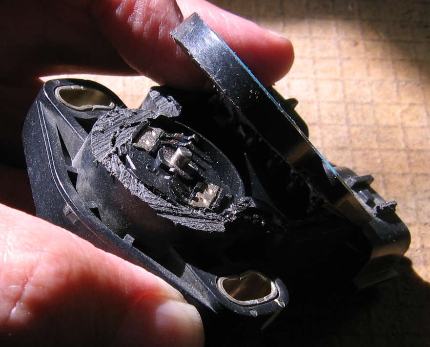
We can see that my educated guess of sawing approximately 6 mm from the back side worked out well indeed: neither the contacts nor the resistive surface were destroyed.
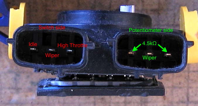
The outer periphery semicircular segment on the right in the photo is a 4.5kΩ resistive element, with the two ends of the potentiometer connected to each of the outer connector contacts on that side. The wiper contact is the nearest matching inner periphery semicircular segment, connecting to the middle contact of the connector on that side.
Over on the other side, we have switch contacts instead of a resistive element. Once again the middle contact is the wiper connection. The outer contact (away from the middle of the device along the line of connector contacts) is in contact with the wiper when the device is at rest under spring tension, thus is the idle contact. The middle section of the outer segment is not connected to any external contact. The top (in the photo) section is in contact with the wiper when the device is rotated towards full stop, and at full stop, so this is the mostly- to wide-open throttle position, connecting to the innermost connector contact on that side.
It will no doubt help to provide another photo of this conductive element, more clearly showing the individual segmented sections of the outer semicircular segment on the left (in the photo). Beneath that photo is a marked-up photo of the connector, showing which contacts connect to what.
Don’t Do That, Do This
As informative as my exploration was, it destroyed the integrity of this particular TPS. You will not have to do that. You will instead drill a small hole at a safe location within the range of the 24 mm diameter circular contact and active switching/resistive element enclosure.
Before You Start
(For some of you, this will be obvious. For others, not so much, hence i’m typing it out.) To save yourself trouble, before removing your TPS, carefully mark its position in such a manner that you will be able to restore it rotationally to the exact same position upon reinstallation. This will save you the hassle of having to go through the TPS adjustment procedure. On my friend’s truck, we were even able to bolt on the replacement TPS in the same position and the alignment was close enough that we did not need to go through the adjustment procedure! This is an even surer bet when the very same TPS is being reinstalled.
Drill Here
At first i thought that drilling somewhere into the blue back surface, or just adjacent to it, would be the for-sure way to go. Closer inspection once the device was opened up revealed that this would require drilling through the ceramic resistive/switching element on the back—bad idea, asking for trouble and breakage.
After careful study, i’ve determined that the most efficacious and relatively safest option is drilling in from the side, along the rounded edge between the screw mounts opposite the connectors. Study the following annotated images carefully:
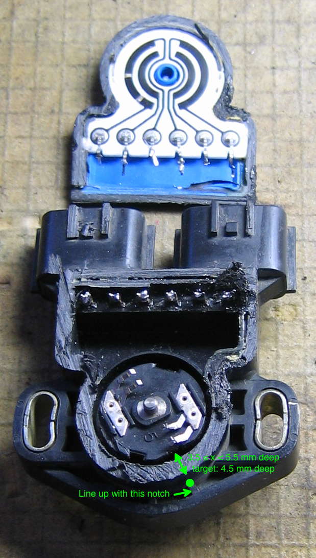
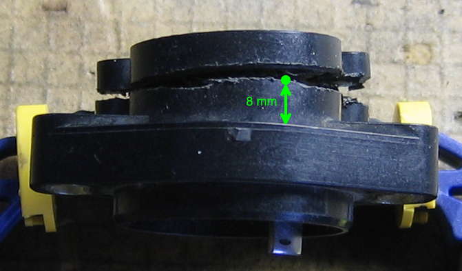
While slightly difficult to see in my photograph (first/top in this section), there is an indentation on the plastic rotary contact/“brush” holder which happens to line up with the rightmost (in the photo orientation) plastic reinforcement notch of the case, on the potentiometer side. This indentation is deeper than the similar notch in the rotary element more visible in my photo, to the left. It also happens to line up with the rotary contacts operating the resistive potentiometer side of the TPS, which are the most likely to need contact cleaning. You will want to drill lined up over this notch. Note that drill depth is critical, to penetrate the case far enough to get the contact cleaner spray in, and not so far as to drill into the plastic rotary contact holder or—worse—bend the contacts themselves. Goal depth is 4.5 mm, with 3.5 being the absolute minimum and 5.5 being the point where you’ll start getting into trouble with rotary element damage. No one said this was going to be easy!
As for height, 8 mm towards the blue back measured from the plane of the surface with the 3 plastic reinforcing notches appears optimal. This is right about near the bottom edge of my fortunate saw kerf cut in the second/bottom photo in this section. Use the smallest twist drill bit that will allow your contact cleaner to get in. Position and drill carefully!
If you have a multimeter and basic resistance measuring skills, before doing any of this you ought to be able to verify that the TPS is at fault. If your TPS is like this one before i cut it open, the resistance will likely jump around quite erratically between the potentiometer wiper contact and either resistance end contact (inside or outside). Drill the hole, spray in the contact cleaner, operate the device by hand repeatedly to distribute the contact cleaner, and test again. Might as well test the switch section too, to ensure it is sending reliable signals. Repeat the cleaning if necessary. Having not actually done this, i do not know how much spraying of contact cleaner will be needed. The potentiometer section may not need much. The switch section, being farther away, may need more.
But what if it doesn’t work, or something goes wrong?
It could happen. If it does, you’re in the same position as the rest of the world who has never read this WWW article: buy a new TPS. At least you tried!
Wrap Up
Once you’ve satisfied yourself that the TPS is again outputting electrically reliable signals, or decided not to bother with the multimeter or similar testing, go ahead and seal up the hole you drilled by whatever means seems appropriate and reliable to you. Dab of epoxy, high-temperature tape… i don’t know what would be best.
Once the hole is filled and the filler has had time to set (if needed), you ought to be able to remount the TPS, plug the connectors back in, restore its position to the one you marked before you removed the device or recalibrate its position per instructions in the vehicle’s service manual or other sources, and enjoy the resumption of steady, stable driving!
If you’ve had success with this method, and especially if you have anything to add that you think other readers of this page might benefit from knowing before trying this on their TPS, email me and let me know, and if deemed appropriate i’ll add your information to this article (crediting you or not, as you prefer).
 World O’ Automotiveness