Chrysler Intermittent (Delay) Windshield Wiper Operation, Troubleshooting, Repair
What They Didn’t Tell You
The documentation in the factory service manual for these systems is pretty good, and there is additional information out there on the Internet which is further helpful. Even so, there were a few important/critical things i did not find. This page is my attempt to fill in the gaps and hopefully help someone else.
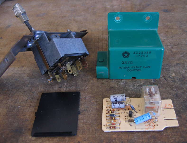
This page covers the intermittent wiper system in my 1981 Dodge B-150 Ram Van with the green plastic “Intermittent Wipe Control” box part number 4222060 (as stamped on the device). Note that the factory parts list shows part number 4048375. I am absolutely certain that the green plastic control unit is factory original in my vehicle. Some people call this assembly the “relay” and there is a relay inside it, but also basic electronic delay circuitry on a small P.C.B. Note that some details will vary between my vehicle and others with different Intermittent Wipe Control part numbers. The basic principles and some hopefully useful information should remain the same. Wiper systems on vehicles where the wipers park in a hidden position below the hood line (concealed) work slightly differently: there is a different pause and park position. On vans like mine the wipers are always visible (non-concealed), thus pause and park are the same “all the way down” position.
TL;DR—Bottom Line
I wasted mountains of time disassembling and messing with the Control Unit before i took the time to understand the circuit. There was nothing wrong with the control unit at all. My problem was resolved by cleaning all contacts on the Dwell circuit. Actually, i cleaned the connector contacts on all of the panel switch[1], control unit, and motor. Additionally, my wiper motor had not run for a long time (years), so merely running the motor for awhile may have cleaned up the contacts enough for them to start working again.
Key points:- The Dwell contact on the motor (on a separate connector) remains closed the whole time the wipers are in the “parked” resting position.
- The timer does not start until the wipers reach the “parked” position.
- A good very low resistance on the Dwell switch when it is closed is essential to proper operation. (Thanks to 440Power’s posts in this thread on RamchargerCentral.com)
Full Principles of Operation, including What They Didn’t Tell You
Some of the following repeats what is well known, in my own words. Some i did not find covered anywhere. Here’s my slightly adjusted/corrected scan of page 8-155 of the Chrysler 1981 Truck Service Manual:
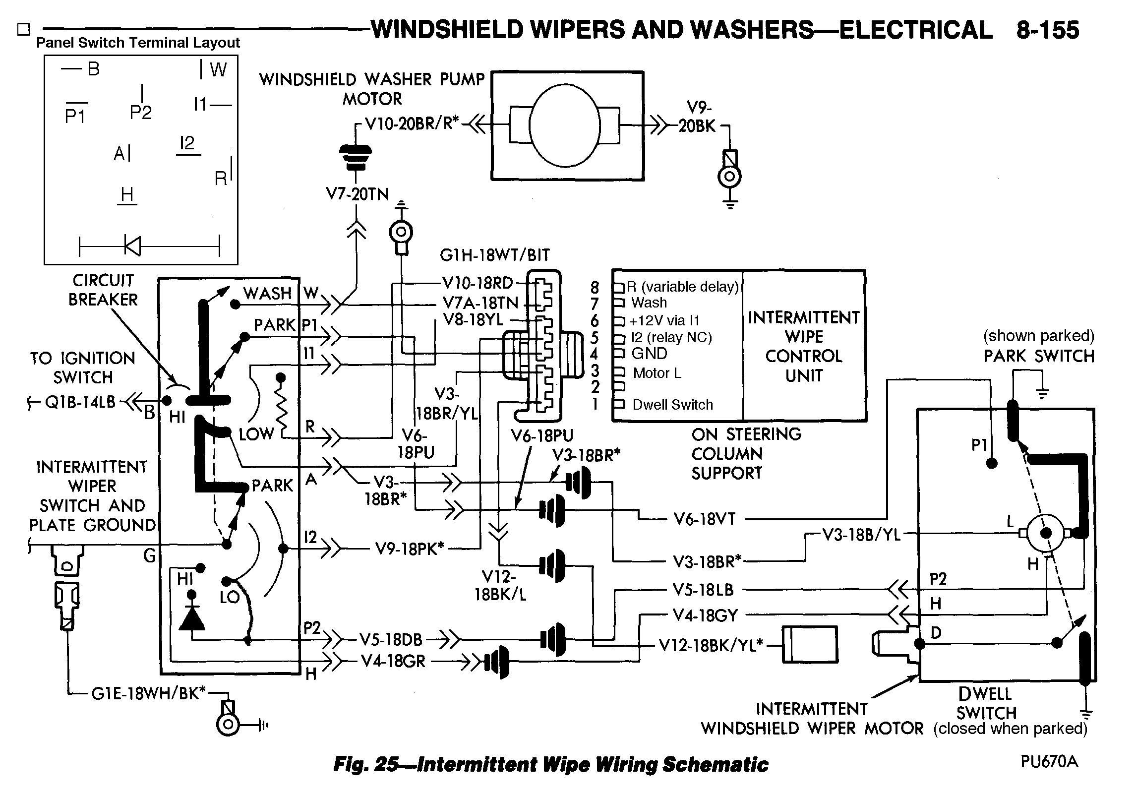
Low Speed Normal
+12V[2] is output on panel switch terminal A, feeding the L connection on the motor. The P2 connection on the motor returns to the switch, where in this setting it is grounded through the switch. Note that many Chrysler wiring diagrams omit the connection between the Ground wiper/LO contact and P2 on the switch. This messed me up for a long time until i figured it out!
High Speed
High speed is never used for intermittent wiping, nor parking. +12V is output on panel switch terminal A, feeding the L connection on the motor, same as for Low speed. Yes, the L as in Low speed connection… stay with me on this. The H terminal on the motor is directly connected to ground through the switch and the P2 terminal is also connected to ground through the diode on the switch.
Off/Park
The motor runs in reverse at low speed until it reaches its parking position. Here’s how that works. In the Off position, the panel switch supplies +12V out of the P1 terminal to the P1 terminal of the motor. Assuming that the wipers are anywhere other than the park position when the switch is turned off, the motor’s P1 terminal goes through its internal Park switch contacts to the unmarked contact on the motor, which is electrically the same as the motor’s P2 contact. Over at the panel switch, P2 itself is open circuit. The A contact of the switch which connects to the motor’s L terminal and supplies +12V in normal Low and High speeds is instead switched to ground. This is similar to Low speed except that the current passes through the motor’s internal Park switch and the polarity is reversed, so the motor runs backwards.
As soon as the motor reaches its parking position, its internal Park switch switches from the motor’s P1 contact to ground. At that point, both the motor’s L terminal (which goes to switch terminal A) and the unmarked motor terminal (which connects to the motor’s and panel switch’s P2 terminal) are both grounded and the motor is braked to a stop and stays stopped.
Intermittent Wipe
Before getting into current flow detail, it is worth mentioning a few fine points of operation that i did not consider until i read about them. I was under the impression that clicking the panel switch into a delay position started the delay timing. Wrong. The point was made (sorry, i did not save the reference to the person who wrote it) that the driver almost always wants the wipers to start immediately, then go into delay. This simulates someone quickly flicking a non-delay wiper control On then back Off. This is a key distinction for properly testing the Intermittent Wipe Control Unit: the delay timing does not start until the initial wipe is finished. In other words, in detail:
- User turns control on to intermittent wipe.
- Wipers wipe once, then park.
- Delay timing starts as soon as the wipers park.
- When the delay times out, the relay in the control unit activates the wipers for another cycle. The process repeats until the panel switch is adjusted.
Chrysler chose to use a separate Dwell switch on the motor. This switch kinda sorta duplicates the operation of part of the Park switch, also inside the motor: both the Dwell and Park switches close the circuit to ground when the wiper blades are in the extreme down-most (parked) position of their travel arc. The Dwell switch is critical to proper operation of the intermittent wiping circuit! Here’s a schematic of the green-plastic-enclosed 4222060 Intermittent Wipe Control Unit:

Four sub-circuits feed into a common point at resistor R8, leading to the base of darlington transistor Q1, which does the actual switching of the relay. R8, Q1, CR2, and the relay are shared in common between all functions of the control unit. R8 is a current limiter to protect the transistor. CR2 protects the transistor from inductive flyback pulses from the relay coil.
Initial Startup: First Wipe
When the wipers are first put into intermittent mode, +12V is freshly applied to control unit pin 6—the control circuit’s B+ line (to use very old terminology). We cannot assume that the wipers have already been running: they may be just now being turned on. If this is the case, the dwell switch on the wiper motor is grounding out pin 1, preventing current from flowing through R2, blocking that path for turning on Q1. C1 is going to take awhile to charge along the pin 8/R1/CR4 path, so we can’t count on it to get things started, and the point of the exercise is a wipe right away with no delay.
R6, C3, and R7 form a kick-start circuit. When the intermittent wipers are first turned on (+12V is freshly applied to pin 6), these components create a positive-going pulse through C3 and R7, to the common point. Q1 turns on, closing the relay and getting the initial wipe started. Note that once C3 is fully charged up, it is blocking D.C. At that point, it, R6, R7, and CR1 are no longer involved in the operation of the circuit. On the output side of the Control Unit, the relay is activated, thus its wiper contact connects to its normally-open contact, leading to pin 6—+12V in intermittent wiping mode. The wiper contact connects to pins 2 & 3, which tie to the A lead of the switch (not in the circuit in intermittent wiping mode) and the motor’s L terminal. P2 is connected to ground through the panel switch in all intermittent wipe settings, same as the LO speed on the panel switch, completing the circuit for the motor to run at low speed (for a single wipe when in Delay mode). As soon as the motor starts running, the dwell switch opens, remaining open through the whole wipe cycle (one motor revolution).
The relay remains activated (via current flow through R5 + R2) until the Dwell switch on the motor grounds pin 1. This immediately cuts off current flow through R2, cutting off any supply of current to the base of Q1 and immediately opens the relay. The normally-closed relay contact through pin 5 of the control circuit connects through the panel switch to ground in all intermittent wiping settings, thus the motor’s reverse EMF acts as a brake, stopping it faster (presumably so it does not overshoot the park position).
Delay Timing
During the previous wipe, the positive end of C1 was charged up to +12V via R5, with the negative end about three diode drops (CR4 and the double base-emitter junction of darlington Q1) above ground—roughly 1.8V. The moment the dwell switch grounds out the positive end of C1, the negative end of C1 slams to about -10.6V. CR4 prevents negative voltages from discharging on any path through the common point effectively isolating the charging path as follows. +12V passing through the variable resistance inside the panel switch continues to exit the switch on terminal R, connected to pin 8 of the control unit. The current passes through R1, slowly charging C1 (eventually in reverse polarity, but don’t worry about that—Chrysler engineers didn’t![3]). Eventually the voltage rises high enough (approximately +1.8V) to turn on Q1 through CR4 and supply +12V on the relay’s output to the wiper motor. The wipers do another single wipe, opening the delay switch during the entire wipe sweep (forward and back). Then once again the Dwell switch grounds out pin 1 and restarts the timer. The process repeats until the user changes the control setting.
Continuous Wipe During Wash
One last function of the Intermittent Wipe Control Unit on intermittent-wipe-equipped Chrysler vehicles of this era is keeping the wipers running continuously on low speed during windshield washing, then dropping back to whichever delay setting was previously in use once the Wash function is released.
The Wash contact of the panel switch supplies +12V to the W terminal, which connects to pin 7 (and to the windshield washer pump motor, which i’m not covering). Directly through CR5 and R3 the +12V forces Q1 to stay on, which keeps the relay energized and the wipers wiping.
There is an additional “extra wipe” once the Wash switch is released, per the service manual. C2 appears to take care of this, all charged up via CR5 and R4 before the Wash switch was released. It discharges through R4, R3, and R8, turning on Q1 for the one last wipe. After that, regular delay mode resumes.
Testing
In-Vehicle Testing Addendum
I am not going to repeat Chrysler’s excellent instructions in the factory service manual (p. 8-151 to 8-155)—too much material with line drawings and so on. I do however have one test refinement to add. They write:
Condition: Wipers Do Not Stop (continue running without delay) when the Panel Switch is in Delay position
- Place panel switch in low speed position. Remove wiring connector from intermittent wipe dwell switch terminal on wiper motor (Fig. 21). Check continuity between the switch terminal and ground. Once in every wipe cycle there should be continuity. Constant continuity or constant open shows a faulty dwell switch in the motor.
Yes this test is important, however i feel it is insufficient. With many meters, including mine, the continuity moment may display too briefly to get a good sense of what is going on. As well, it’s not there long enough to get a resistance measurement, and others have reported this failure from the contacts working but there being too much resistance in the path for the timer circuit to function properly. Without a solid ground for a long enough time, the R5 + R2 path may not drop low enough long enough to turn off Q1 and open the relay. The relay will stay closed and the motor will keep running. Therefore, i recommend the following additional in-vehicle test:
- Under the conditions of step 1, place panel switch in the Off (park) position. Allow the wiper motor to park itself. Measure the resistance between the motor’s Dwell terminal and ground. If it is greater than about 5Ω, you’re likely to have problems.
I made up the 5Ω number—it’s a guess. The threshold for my particular control unit was 65Ω. I put a potentiometer in series with my test-bench dwell switch, and this was the resistance on the edge of mis-operation under laboratory conditions. Note that poor contacts leading to excessive switch bounce may be a problem at lower resistances. Further note that as resistance goes up, there is a human-noticeable delay before the relay releases, when the dwell switch closes. Around 65Ω i noticed plenty of time—a good half second or so—such that the momentum of the motor/gear drive could easily keep the motor running long enough to re-open the dwell switch contacts before the circuit dropped into timing mode.
My particular wiper motor—working—measured 2.6Ω from the Dwell terminal of the motor itself to one of the motor mounting bolts (i got about the same result from the terminal to the negative battery terminal).
I should mention that the resistance readings under 10 ohms in this article have been reality corrected. My Fluke 77 multimeter + its test leads have a residual (self) resistance of 0.3Ω. Therefore when i write that it measured 2.6Ω, my meter actually showed 2.9Ω. Every meter is different—be sure to check yours!
This is with having made no attempt to clean the dwell switch contacts themselves, nor the motor’s grounding. I noticed that i could hear the Control Unit relay bouncing: sometimes doing a double-click. I do not recall having heard that in the past. I eventually decided that with everything apart and all my tools out etc., i might as well redo the motor ground and remove, clean, and adjust the motor’s Dwell Switch. The combination of these two procedures dropped the resistance to 0.7Ω.
Anyone who’s skilled with an ohmmeter and wants to add higher resistance values which still work or lower values which fail to our collective knowledge, write me and i’ll see about adding your information here.
Dwell Switch Notes
I did not take photos, but i do have a few notes about the dwell switch. The white plastic switch assembly holds one (1) springy metal (phoshor bronze? Something like that) contact, which goes to its terminal lug. The actual contact surface is in the middle of the contact assembly. It looks like it can work on either side, but at least in this motor, the active contact is on the outside (facing away from the center of the motor). There is a fixed contact inside the gear assembly which is rigidly fastened to it. It does not come out and i made no attempt to remove nor adjust it.
In the Park position, the contacts are at rest and closed (normally closed). When the motor runs, a plastic ring-like part high up in the gear assembly pushes the movable dwell contact (the one which is removable, on the white plastic base, a.k.a. the dwell switch proper) away from the fixed contact, which is to say, in towards the center of the motor. Therefore, the least amount of stress on the dwell switch is when it is removed with the wiper motor parked.
Something else i noticed during this procedure is that, with my ohmmeter connected, if i pushed the dwell terminal towards the outside of the motor, the switch would open, even with the motor off and in park position. There is not much play in the mounting of the dwell switch, but there is a little, therefore i adjusted the switch to minimize this effect. In other words, i adjusted it for most reliable and lowest resistance before screwing it down, then re-tested it. Being on the edge of not working may have been my original problem: it did not take much to open the circuit with the motor parked.
Site correspondent John M. corroborates and adds some sage contact cleaning chemical advice:
My problem was “wipers continue running without delay when switch is in the delay position”. I went straight to the dwell switch and found a high and erratic resistance when closed.
The cause of the high resistance was the connector of the dwell switch. It is actually made in two pieces, a copper piece and a bronze piece that are riveted together. The rivet also holds this connector assembly in the plastic body of the dwell switch.
The joint between these two pieces was loose and corroded. I cleaned them and then soldered them together. Then I put the assembly back into the body of the dwell switch using a machine screw in place of the rivet.
One further thing I recommend for getting low resistance contacts: Stabilant 22. I have had much success with this product on mature vehicles.
After all this, all the functions of the wiper switch are perfect. The closed resistance of my dwell switch is 0.1 ohms, NOT correcting for the meter’s residual resistance.
Impressive results indeed, on a lovely one-owner 1982 Plymouth Voyager B150! (Note to self: time to try some Stabilant. Caig products aren’t always the most suitable in all instances.)
Bench Testing Intermittent Wipe Control Unit
Some vehicle owners posting to other sites (such as 440Power mentioned above) note that their control unit was not the source of the failure, and it certainly was not mine! I strongly recommend looking elsewhere for trouble: clean all connector contacts, plus the dwell switch contacts, plus the motor ground. If that doesn’t fix the problem or for any other reason you’re quite sure you want to test your unit, the following information may help. It may be easier to test with the panel switch (especially the delay), but it is not necessary, especially if you have a 330kΩ or so potentiometer available.
You will need:- 12VDC power supply (anything 10 to 15V should be OK)
- Various alligator clip leads or other means of wiring attachment
- 330kΩ or greater potentiometer/variable resistor, or the vehicle’s panel switch
- Some flavor of S.P.S.T. switch to act as the Dwell switch
- A light bulb, meter, or other 12VDC-compatible indicator of when the wiper motor ought to be running
- A second momentary or regular S.P.S.T. switch for use as the Wash switch (or just use the vehicle’s panel switch)
Setup
I chose to remove the circuit board from the housing, mostly because i had not thought things through critically and ASSumed the electronics were at fault. See below for disassembly instructions if you too want to get the board out of its enclosure. Because i could see the relay contacts moving, it was not necessary for me to connect any sort of run indicator.
- Connect power supply common (which i will hereinafter call “ground”) to pin 4 of the control unit.
- Connect the Dwell switch between pin 1 and ground. Start with the switch in the closed position.
- Connect the Wash switch between pin 7 and +12V on the power supply if you are using one (you could instead use a clip lead).
- If you are using a motor run indicator, connect it between pin 3 of the control unit and ground.
- Prepare to connect +12V to pin 6 but don’t connect it yet. Or, turn off the power source and connect it.
Testing
Initial Test
Apply power. The relay should immediately close. Leave the dwell switch closed: the relay should open after about 1.6 seconds and stay off. This proves that the kick-start circuit is operating properly. Remove power and wait at least 10 seconds before the next test.
(Re-)Apply power. The relay should immediately close. When it does, open the Dwell switch for about two seconds then close it again. The relay should immediately open and stay open. This is an intentional external failure mode: there is no variable resistance connected yet, therefore C1 cannot charge and the time delay is infinite. Remove power.
Full Delay Test
Connect variable resistance between +12V and pin 8, set to highest resistance. Apply power and follow the steps of the initial test, leaving the dwell switch closed. The relay will immediately close for about 1.6 seconds as before, then open. It will stay open for a wildly varying amount of time, depending upon the charge of C1 and maybe other factors. It will then close again and stay closed. Verify that this is what happens. This simulates a shorted dwell switch.
Continuing from above, open the dwell switch for at least 2 seconds, then close it again. This time the relay should immediately open when the dwell switch is re-closed, then eventually close again in roughly 10 to 30 seconds, possibly longer if the resistance is higher than 330kΩ. When it closes, again mimic the proper operation of the motor’s Dwell switch via opening it for a couple of seconds (one wipe cycle) then closing it again, repeating during the test. Adjust the variable resistor to a lower setting: the delay should be shorter. At zero resistance there is basically no delay.
Wash Test
Set things up as for Full Delay Test, with maximum resistance (longest delay) and the dwell switch closed. In addition add a Wash switch between pin 7 and +12V (or simulate one with a clip lead or whatever). During the time the Wash switch is activated, the relay should remain closed, no matter what the Dwell switch is doing. When the Wash switch is released, there should be one final wipe then the pre-existing delay wiping should resume.
If any of the tests fail (and you are quite certain all your external wiring and equipment is functioning properly), you have the choice of replacing the Intermittent Wipe Control Unit or doing component-level troubleshooting and repair of the one you have (beyond the scope of this web page).
Removal of the Intermittent Wipe Control Unit
This is one of those things which, at least for me, proved wholly, completely, unnecessarily difficult. The control unit is a lightweight device, held securely to the steering column by two #2 Philips-head screws. Removing the lower trim is not my idea of recreation, but isn’t bad. Holding in the two latch clips on the 8 cavity connector plugged into the control unit and wiggling out the connector is the usual deal. The problem was those two screws.
In a sane world, i would have been able to use one of several “trick” angled screwdrivers i have to unscrew the screws and get the unit out without further disassembly. Nope… the screws were installed too tightly. So, i had the extra pleasure of disassembling the dashboard. Conveniently there was just enough of a gap for me to get my lovely Snap-On SSDP 216 extra-long Philips #2 screwdriver onto the screw heads with a nice straight shot. Nope… thought i was going to torque the screwdriver blade beyond reason, and the screws were not cracking/budging.
Disconnected the battery (grumble), removed the instrument cluster (grumble, gripe, grumble). Now there was nothing in the way of my having a nice, clear shot for my vintage Fiskars Screwball interchangeable-tip screwdriver with the wonderful rubbery handle to do the job. Those screws were in there crazy-tight: it took every bit of strength i had to crack them free (then unscrew them normally)! The installer must have had a torquey power driver set to Stun when s/he drove those two screws home! There is absolutely no reason for that much torque on fasteners holding such a lightweight, non-moving, not-critical-if-it-shifts device! Maybe the dendrites between the screw and chassis bracket metal grew to love one another over the years more than usual. Whatever the cause, those two screws were bastards to get out.
All of this is my way of saying if you are just starting troubleshooting and are not certain that the control unit is defective, don’t remove the control unit! Search the WWW/Internet first for the many anecdotes of people who have replaced their control units and found that doing so failed to fix the problem. If you do have a legitimate need to get the box out, prepare for possible unnecessary difficulty.
Disassembly of the Intermittent Wipe Control Unit
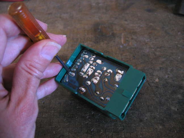
Getting the printed circuit board out of the green Control Unit enclosure is pretty easy. Some of you will know how to do this via prior experience and/or mechanical intuition. Never hurts to have a sanity check, so here’s what i did, with pictures:
- Gently pry the edge of the black cover away from the holding latch on the green case
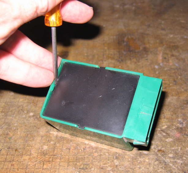
- Lift the black cover at the prying end enough for the side tabs to clear the green case and pull out the black cover, pulling away from the connector
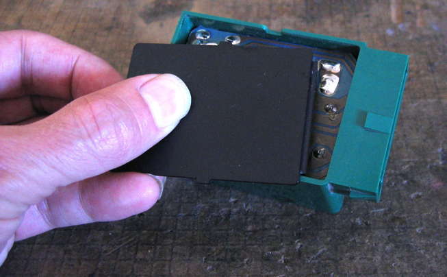
- Pry the circuit board out in the same manner and from the same side as the black cover. This latch is stiffer: flex the case, not the P.C.B.
- Remove the P.C.B. similarly to how the black cover was removed, other than there are no other latches/catches (no picture of this)
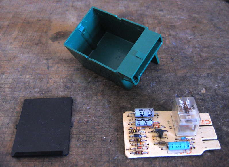
Notice the lip on the black cover. This presses against the connector edge of the P.C.B., holding it in place. When it comes time to reassemble the control unit, be sure this lip is inside (near the P.C.B.) and at the connector end.
I found that my control unit rattled when reassembled and remounted to the steering column. It probably did so before and i did not notice. I like to minimize the amount of noise in my van (as if!) whenever possible. Therefore, i applied small dabs of hot-melt glue to each corner of the P.C.B.-green case interface, then quickly reinserted the black cover. The glue was still soft enough to adhere to the cover as well (on the inside), making for a nice, tight, rattle-free package. Because the two fastening screws are at the same end, there can also be a bit of rattle of the overall case at the end opposite the screws. I hot glued a thin strip of rubber i had lying around to this opposite end. The final result is much quieter than before. Will it matter in a noisy vehicle? Probably not, but i figure every little bit helps.
[1] “Panel switch” is what Chrysler calls the washer/wiper user control assembly on the dashboard. A synonym would be the control switch. If i fail to mention some other switch in this article, like the Park switch or the Dwell switch, i’m talking about the panel switch.
[2] Throughout this article i am using +12V to indicate vehicle battery/alternator power. Clearly the actual voltage will vary over the usual range of the vehicle’s electrical system. Think of it as B+ or main power or whatever else you like, if you prefer.
[3] I am confident that Chrysler engineers researched and took into account real-world considerations regarding reverse polarity at low current for limited amounts of time on C1. The fact that many of these circuits continue to work 35+ years after manufacture is a testament to both their design work and the quality of the capacitors. When the delay mode is operating properly, C1 spends most of its time with correct polarity across it, thus the Chrysler engineers did the correct thing.
 World O’ Automotiveness