Originally Web posted 8 July 1996.
Content last modified 21 June 1999.
External links last verified 30 January 2005.
Sonic Purity—former KALX Staff Engineer
Once in awhile, a dream comes true. Such was the case when KALX switched from an RCA BC-7A console to a PR&E BMX III a few years ago. As is often the case, there wasn’t money left over for other new equipment, such as turntables. Given the changes in availability of broadcast-quality turntables, even well-to-do stations using vinyl are finding the Technics SL-1200 MK 2 to be a viable option, perhaps the only option.
While the SL-1200 MK 2 is a fine turntable, it lacks the remote start/stop capability expected of a true broadcast turntable. As pointed out by Radio Guide’s fearless editor George Whitaker in the April 1992 Tech-Tips column, it is simple to parallel the internal start/stop switch for basic remote control. However, it would be nice to enable the full capabilities of the remote logic of today’s sophisticated consoles by providing the missing run/stop “status” signal return from the turntable. As we shall see, obtaining/creating this signal is fairly simple.
The PR&E TT-3 Turntable Interface for the BMX-III series of consoles is set up for members of the Technics SP series turntables, providing a single optoisolated contact closure for start/stop, and requiring a “run” signal from the turntable capable of driving the LED in an MCT-2 optoisolator (presumably, the requirements of other like consoles are similar). The question is, where is the “run” signal?
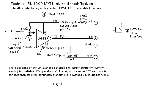
A comprehensive investigation of an SL-1200 MK 2 with an oscilloscope and schematic revealed the disappointing news that there was no “pure” run or stop signal available to the outside world (it’s inside IC 201, the AN 6680 Control IC). Undaunted, the investigation continued, and revealed that the Vo line (pin 13 of IC 201) was the closest viable option, going high (around +5V) as the platter commences rotating, and dropping low (≈+.2V) when it reaches a standstill. As this line is very sensitive to loading, some buffering is necessary.
The first attempt used an MPS-A13 darlington, but even this was too much of a load. The first version final circuit (fig. 1) uses an LM 339 comparator IC. All four comparators in the IC are paralleled to provide ample drive to the LED in the optoisolator (and because they weren’t going to be gainfully employed otherwise). The Vo line load is sufficiently low that the turntable displays no signs of unhappiness.

This circuit was in use between October 1989 and September 1992 on two SL-1200 MK 2s feeding a (virtually) stock PR&E TT-3 interface, with no reported failures despite heavy 24 hour use (KALX still airs a high percentage of vinyl). The only problems were loose connections upon initial installation (i’d never crimped Molex®es before), and the occasional heavy-handed programmer who stalls the platter while slipcueing (they learn soon enough). One minor, but possibly annoying, side-effect of using the Vo line is that the “Ready” (Off) lamp on the BMX flickers as the turntable platter draws to a stop (the comparator is toggled by the settling Vo line). While disconcerting, it is not a problem, and is actually a useful indication to the programmer that s/he needs to lighten up on the slipcue grip, or suffer a “wow” start.
The comparator circuit was assembled on a tiny scrap of perf board, and installed in the 1200 adjacent to IC 101, using one of several unoccupied standoffs Technics so thoughtfully molded into the chassis. A length of 3-cond. + shield scrounged from a local surplus outlet brought the control lines to the outside world, exiting the 1200 through the hole next to the A.C. cord (the cables i found came with their own strain reliefs!).
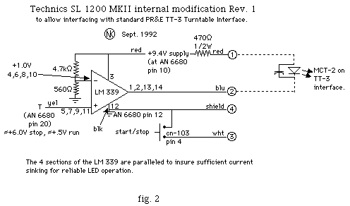
Revisiting the situation in 1992 in an attempt to cure this minor aberration, it was found that the T line on pin 20 of IC 201 (same as left end terminal of VR 201) provides a stable run/stop status indication, independent of platter stalling. The possible drawback here (and the reason this line was ignored during the initial inquiry) is the time constant ramping from run->stop used for braking. Careful testing revealed this to be a non-problem, as this time constant is shorter than the typical toggling of the comparator by Vo during platter wind-down, and is thus harder to falsely trigger (during extremely rapid on-off-on sequences sometimes used for effect) than the original design. Changing the comparator threshold to 1.0V staved off any difficulty.
One might also be concerned about the degree to which the logic thresholds are affected by the Brake adjustment (VR 201). The answer: hardly at all. On a typical SL 1200 MK 2, the T line ranged from ≈+5.8-6.5V in stop mode, and +.3-1.5V running over the full range of the Brake trimmer, with most deviation at the extremes. Typical values with VR 201 correctly adjusted for fastest braking with no kickback: +.5V run, +6.0V stop. The +4.7V threshold would provide plenty of margin for correct mode detection over the entire VR 201 range, but a long run-> stop transition. For best results, pick the lowest threshold with which you’re comfortable (i use 1.0V).

The T line seems relatively sensitive to external loading, but not quite to the degree of Vo. Experiments with resistive loading show T getting dicey around 50 kΩ to common, so those planning alternatives to the LM 339 should think high beta, and at least 82 kΩ build-out. The original comparator setup was retained (with a polarity flip corresponding to the T line’s logic inversion) as it was already in place. This incarnation has been in 24 hour service since September 1992 on two heavily-used 1200s without any reported failure or problems.
With the simple addition of either of these circuits, cabling and connectors, and any standard logic interface required by your console, your facility can enjoy full-function remote control of the Technics SL-1200 MK2.