1/2AA Mac PRAM Battery Accessibility Modification
Pictorial of the Crazy Insane way i did it, with suggestions for how you can do the same thing more sanely
Apple hardware engineering has been rightfully praised over the years for many innovations, some occasionally bordering on magical. Other times hardware decisions, whether made by engineering, design, marketing, or Mr. Jobs (when he was on the scene) leave one scratching one’s head, wondering What were they thinking?!.
Placement of the PRAM battery holder on certain Macintosh models often falls in the latter category. Recently resurrecting a 9500/233 (at least it’s a 233 MHz with an aftermarket CPU card when i received it) and being reminded that one has to disassemble the entire machine and remove the main (logic) board to access the 1/2AA 3.6V PRAM battery falls squarely/cleanly in the latter category of hardware design. What were they thinking?!
Remote-ing the Battery
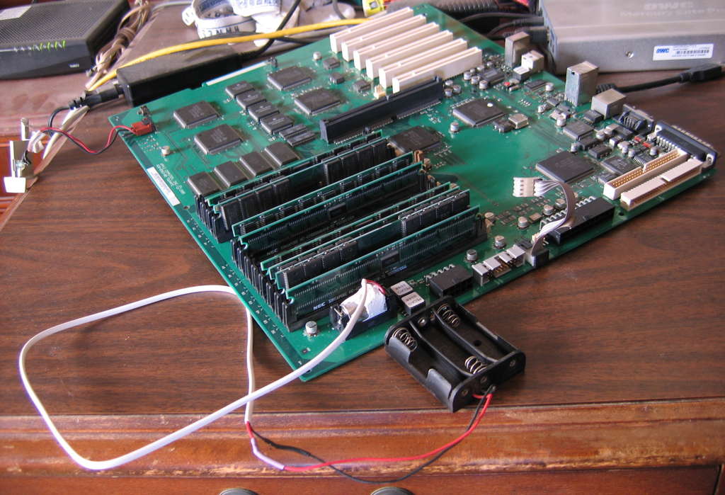
I decided that at least for this particular machine, i’d “remote” the battery, which is to say, install an ersatz non-battery in the inaccessible 1/2AA battery holder, acting as a pair of contacts with wires attached. The long wires would lead to an accessible battery holder. Moreover, given that this is a seldom-used testing machine for which i prefer not to invest in keeping working official 1/2AA batteries installed, i chose a standard 3 AA cell battery holder for the remote end. More on how that all works out to 3.6VDC near the end of this saga.
The Sane Way (the path i did not take)
Soldering wires onto the existing 1/2AA battery holder is obviously an option, and indeed i did that on a seldom-used 6100/60 in my collection. Tacky, and depending on the soldering job, not necessarily 100% reversible. Didn’t want to do that this time around.
It would make a lot of sense to grab a wooden dowel about the same diameter as a 1/2AA battery, cut it to length, drive in a couple of suitable nails at the ends, solder the wires to the nails (before driving them all the way in, then driving them all the way in, and calling it good. Or maybe use plastic or some other insulating material instead, and whatever is lying around that’s suitable for electrical contacts which will mate with the stock battery holder. Any variation on this theme would be faster and safer than what i did, and should easily work every bit as well.
My Crazy Method
Take Apart A Dead 1/2AA Cell, to be the Ersatz Battery
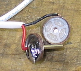
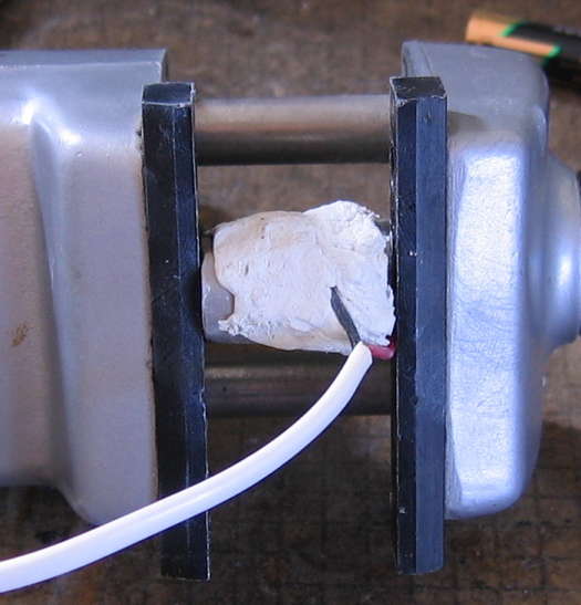
Alright, i guess what it comes down to is i wanted to take apart one of these batteries to see what was inside. First i took off the outside wrapper, then the plastic top insulator:
In case anyone’s wondering how the original battery design works, there is a small insulator around the center pin/shaft/tip, isolating it electrically from the periphery of what after i cut it apart is the circular top. The original plastic green insulator is very necessary to prevent shorts between the tip and the adjacent metal circle of the (intact original) battery body.
Build The Ersatz Battery
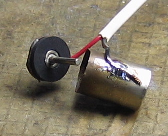
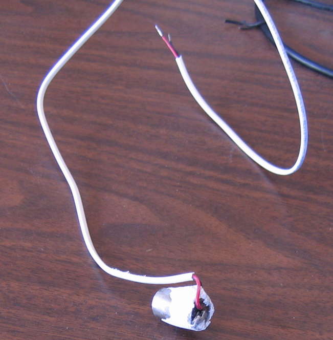
It took me a long time to figure out how i wanted to handle attaching the wires and reassembling the original battery bits with reasonable insulation and as close as possible to the original exact length—time which in retrospect would have been better spent using a different, easier method (discussed above). Here is how i finally decided to deal with attaching the wires:
Not pretty, but it gets the job done. Note that i used a long length of 2 conductor cable, to get the remote battery holder to an accessible area of the 9500 chassis. Also note that i chose to short out the original insulator with a massive solder bridge, making the the entire top the positive connection. This choice required that i add insulation along where i had sawed the original battery apart—a point where there was no insulation with the original intact battery. In part i made this choice so i would not have to be concerned about melting the original insulator, given that the metal materials of the battery were not readily taking solder.
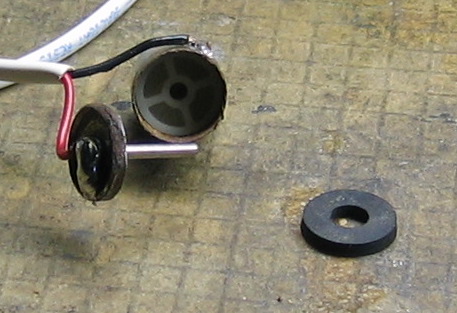
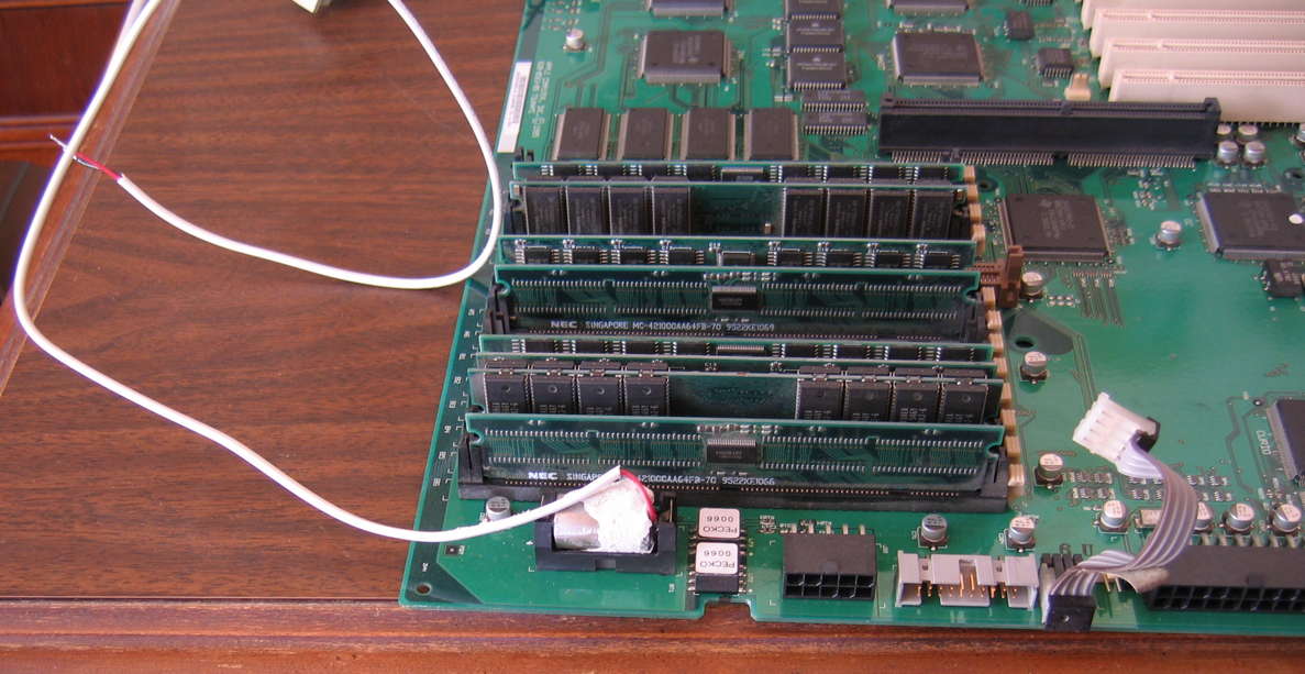
One great bit of fortune i had was finding a ready-made interior insulator in my standoffs collection, to help stabilize and insulate the center shaft. I attribute this good fortune to most of the world being sane and using the metric system, and both the battery and this standoff being metric-dimensioned. This picture not only shows the standoff, but also a close-up of my tacky soldering job:
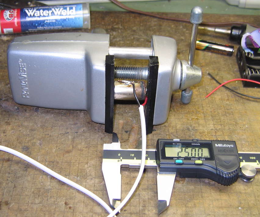
’Splain the 3 AA Batteries, and How You Can Possibly Get 3.6VDC
One option is to use 3 rechargeable AA batteries. The chemistry of these tends to have them putting out 1.2V apiece. 1.2V x 3 = 3.6V.
Do you think i did something that obvious and reasonable? Of course not! I chose to go through my vast collection of weak standard 1.5V AA batteries, hand-selecting those right around 1.2V actual output. Put in 3 of those, and it was a little high at 3.7V, but close enough—and it will only go down in voltage, not up. I have no shortage of these (long story), and they’ll likely last longer than rechargeables before needing to be dealt with. But even if i’m mistaken on that, at least now the battery holder is readily accessible!