Reviving a Dead HP DeskWriter Printer
While the Hewlett-Packard (HP) DeskWriter (Mac) and DeskJet (PC) 600 series is quite old, there are some cases where one may want to revive a dead printer rather than buy a newer model. In the case of the DeskWriter 660C that is the subject of this article, it is a serial printer, required by older Macintosh computers. Serial printers have not been available new for many years, so even a fairly involved repair may be worth considering, assuming one wants to keep the older Mac system running and able to print, as was my circumstance when i wrote this article.
Determining the Source of the Deadness: Will This Page Help?
Many possible failures can cause the symptom of a totally dead printer. This page focuses on the case where the power switch itself is nonfunctional. First, one needs to determine the source of the deadness.
- Disconnect the data cable between the printer and the computer. Check the obvious: Does the electrical outlet for the printer’s power supply actually have power?
- Unplug the power supply at the printer end, with the other end still plugged into active A.C. power. Measure the voltage with a voltmeter: It should be about 36VDC. (It is rated 30V, yet this measurement is without its normal load, so a higher voltage is expected.) If the voltage is much below 34V or over 38V, the power supply is likely defective. Conventional repairs (not covered on this page) should fix the problem.
- Power switch test:
- With no cables connected to the printer, remove the back cover “bulge” by releasing the two locking tabs under the unit and “hinging” the cover up (the top edge has two plastic tabs acting as the “hinge”).
- Facing the rear of the unit, there is a connector in the upper left corner of the printed circuit board to which a flexible PCB “cable” attaches. This connector has 6 contacts, or “pins”, with pin 1 on the right side (from the PCB component side). Prepare a jumper wire of some sort which can momentarily connect pins 5 & 6. This simulates the action of the power switch.
- Lift the two locking tabs on each end of the connector, and unplug the flexible PCB cable.
- Connect the already-tested and known-good power supply to the printer and to A.C. power.
- Momentarily connect (“short”) pins 5 & 6 and release.
For further confirmation that the power switch and/or wiring is the problem, one can attach an ohmmeter or other continuity tester to pins 5 & 6 of the flexible PCB cable. There should be an open circuit except when the power button is being depressed, in which case there should be little resistance… certainly 100Ω or under. An always-closed circuit (unlikely) would indicate a stuck power switch or shorted wiring. An always-open circuit (extremely likely) would indicate a wiring and/or switch failure.
OK… Confirmed Switch and/or Wiring Failure… Now What?
To find the actual defect, it will be necessary to open up the unit. No pictures for this operation here.
- Disconnect all cables and remove any paper.
- If the rear “bulge” has not already been removed and the flex PCB cable already been unplugged from the testing steps above, follow those steps now.
- Remove the Out tray.
- Unscrew the two Torx T-15 screws visible in the vicinity of the In tray.
- Flip the unit over. Start unlatching the many plastic tabs and lifting the bottom metal plate off.
- Flip the unit over. Carefully and slowly lift the case off of the mechanism. Note: there may be other obstructions that i have forgotten, so use care and common sense!
- Remove the 3 metal rectangular spring clips holding the PCB flex cable to the upper plastic case. These should slide sideways then come off easily.
- Unsnap the switch panel from the remainder of the plastic top case. Note: there are latches or hooks on 3 sides, so proceed carefully. They may be stiff, yet they should not break.
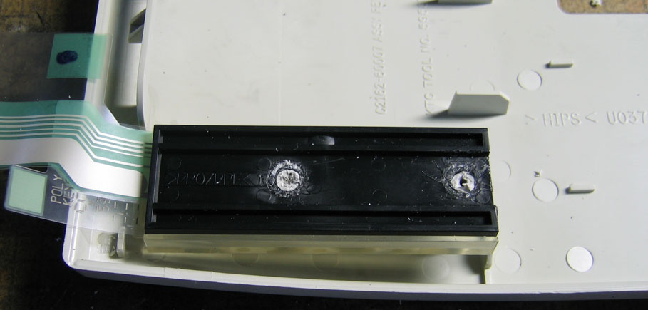
Look very carefully at the PCB traces: chances are excellent that some of them have oxidized, at least over portions of the cable, and are no longer conductive. This certainly was the case with my DW 660C:
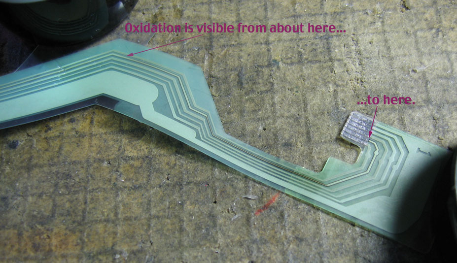
(Click on image for larger picture)
In the case of my printer, the entire length marked in the photo of the trace connecting to Pin 5 had oxidized and become nonconductive: an open circuit. Same result as if the power switch itself failed: Dead Printer.
If the damage is restricted to a smaller area, an easy and suitable repair can be effected via a conductive pen, made for just this sort of PCB trace repair. Not only was the damage in my case over a very long run, other traces were beginning to show signs of oxidation (not visible in the photo). This whole section of flex PCB would have to be cut off and replaced with actual wire.
As i attempted to solder onto the remainder of the flex PCB conductive traces at the switch end, i discovered that no matter how careful my technique and soldering iron adjustment (and mine has quite a range), i was unable to reliably make a connection. Usually the PCB plastic melted, even at very low soldering temperatures just barely able to melt the solder. Another approach was needed.
Removing the Original Switches
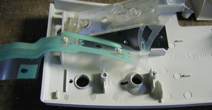
As the flex PCB disappeared into the original switch assembly, the latter needed to be disassembled to further investigate options. As is typical, this printer series was designed for low manufacturing costs and no thought of repair, to keep retail costs competitive. As such, the switch assembly was permanently attached via plastic posts with melted tops as fasteners. These needed to be chewed away. I chose diagonal cutters, with this result:
(Click on image for larger picture)
Pulling the switch assembly off the posts and apart, we see:
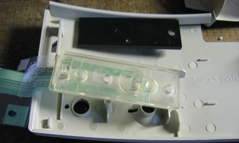
The button innards and the LED lenses are all part of one single piece of clear plastic, flexible in places. Digging deeper, we find:
(Click on image for larger picture)
Bummer… the switches themselves are made from the flex PCB material! Great for HP and the original purchaser’s pocket book… not so great for us. And the LEDs and series current-limiting resistors are directly soldered to this flex PCB…… sigh.
Making Life Easier and More Reliable: Replacing with Durable Switches, Leaded LEDs, and Actual Wire Cable
At this point, any reasonable switch and LED arrangement may be considered. Cost, ease of installation, parts availability, and final appearance may all be potential considerations. Fortunately, i have a fairly decent stock of electronic components salvaged from abandoned “consumer” electronics and similar sources. HP apparently designed the switch panel case front to accept standard LED dimensions… i soon found one green rectangular Power LED and one amber round Resume LED in my stock. For the switches, i chose some actual mechanical switches commonly used in this sort of equipment:
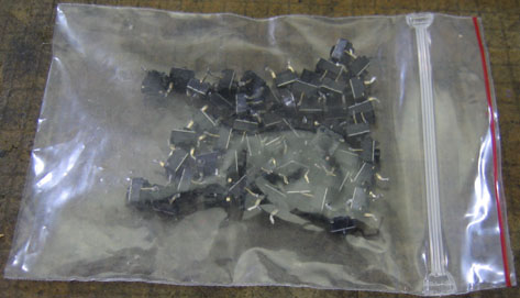
Sometimes known as “tact” switches, these are miniature SPST momentary pushbutton switches, designed to be inside equipment and activated by human-sized buttons. I figured (correctly) that two of these could be fastened to the former back piece of the original switch assembly, and be activated by the original buttons, with minor modification. Measurements were made, and holes drilled in the original back piece for both the switches and the LED leads. The switches were fastened with hot glue:
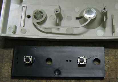
Notice that the switches are mounted on the front-facing surface of the original back plate, where the flex PCB and the clear plastic used to be. This picture also shows the modification to the original “human” plastic buttons, namely clear, thin, flat sheets of stiff plastic held in place by…… wait for it…… hot glue. Here is a side view of those “button flats”:
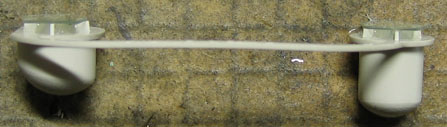
The purpose of the “flats” is to provide a reliable contact surface to operate the actuator on the “tact” switches. These modifications necessitated a change in the height of the back plate in relation to the front panel. Namely, the back plate needed to move farther back to allow for the extra thickness of real switches. This distance was established with round shims, made of removed plastic cable insulation. These can be seen in the picture below, colored gray, along with the hot-glued (and, for the round LED, force-fit first) LEDs:
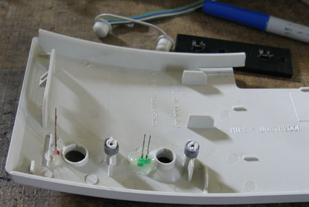
Each LED needs a series resistance, as for the originals. The original chip LEDs were supplied by what appear to be 1% chip resistors. The green LED was fed by a 267Ω resistor, and the amber LED by a 243Ω resistor, probably to equalize optical output levels, or to make the Resume LED brighter. Whatever the case, i chose to use the closest standard 5% 1/4W axial lead resistors i had, which were 270Ω and 240Ω, respectively.
For cabling, i chose some rainbow ribbon cable i happened to have on hand. Any small-gauge 6-conductor wiring that stays neatly bundled so it will not wander around and interfere with the printer mechanism should be suitable. The length should be about as long as the original PCB flex cable. The ribbon cable conductors were wired in the same order as the original flex PCB “cable”, to make connection at the main board end easier.
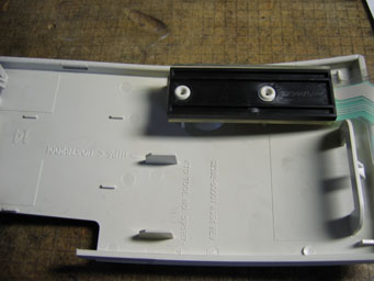
To fasten the back plate into place, i used some plastic-thread (very coarse thread) 2.6 x about 6 mm Philips-head screws with wide flat washers. These fit nicely into the existing holes in the original mounting posts, once the new threads were cut. The final assembly looks like this:
The switch panel was now snapped back into the rest of the plastic case. The ribbon cable was routed along a direct path to the main PCB, while staying out of the way of the mechanism. It more or less followed the original wiring path:
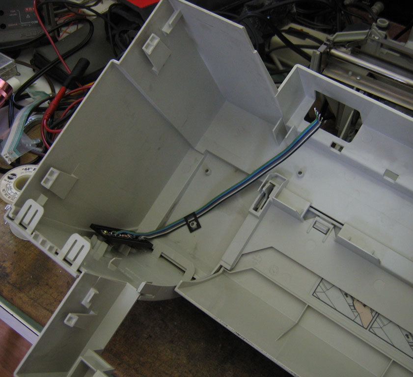
(Click on image for larger picture)
Only one of the three original springy mounting clips was used. It was installed by sliding it in the opposite direction used for removal. At this point, it is a good idea to temporarily replace the plastic case over the mechanism, and attach the ribbon cable at the main PCB end, in case there has been any miswiring on the switch board.
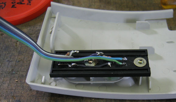
In the ideal world, it would be a good idea to have the ribbon cable attach to the main PCB via a detachable connector, as with the original system, for easier servicing. Not having such a connector, not wanting to order one, and not being too concerned about future access to the insides of this already very old printer, i chose instead to remove the original connector (which was designed for flat flex PCB material and not actual round wires) and carefully solder the end of the ribbon cable directly to the main PCB. Here is the result:

(Click on image for larger picture)
It would be wise to verify correct wiring and no opens or (especially) shorts between pins.
Now it is time to test the printer for basic operation, before final assembly. Carefully position the printer in a way that allows viewing and using the front panel lights and switches. Open the cover and look very carefully at the back of the newly-modified switch panel and the rest of the printer mechanism: i had to reposition some of the ribbon cable wires and resistor ends to avoid mechanical interference. Look over the whole length of the replacement wire cable and resolve any possible mechanical interference problems with the rest of the printer mechanism. Connect the power supply to the printer and A.C. power. Press the power button: the printer should start making its usual noises, the Resume LED should briefly flash, and the Power LED should stay illuminated. Pressing the Resume button should cause the Resume LED to illuminate. If any of these operations fail, carefully re-check the wiring for continuity and freedom from shorts, and verify correct LED polarity.
Once the basic functional check passes, re-assemble the unit, starting with the bottom metal plate, and continuing in reverse order of disassembly. Before snapping the rear “bulge” cover for the main PCB back into place, it may be a good idea to re-verify the basic functions listed above. (In my case, some wires broke loose at the main PCB. If i had it to do over again, i would seek out smaller gauge ribbon cable with smaller and more flexible conductors.) With the unit reassembled, print a test page and otherwise verify normal operation. Pat yourself on the back for a job well done!
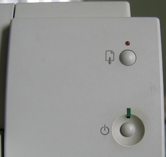
The final result of my modification looks nearly identical to what originally emerged from the factory:
Value of a 17+ year old 600 DPI inkjet printer: Minimal (arguably zero in some places).
Value of the personal satisfaction from a repair well done, and keeping usable electronics out of the e-waste stream awhile longer: Priceless.