The Clicking and Blipping Adventure
Just because you’re an Electrical Guy, not every failure is electrical!
Failure Background
While visiting the home (in which i grew up) over the December holidays (2008), i noticed that the central attic furnace, a Day & Night-badged 376B (specifically, a 376BAW036075), was making “clicking” sounds. Upon further investigation, the clicking was coming from the burner chamber, and coincided with the main burners “blipping” off momentarily, then bursting back on and continuing to burn normally, until the next “blip” and simultaneous click. The pattern was totally random. The failure would only occur when the furnace had been running for a few minutes (in other words: temperature-related failure), and would continue until the heat call cycle eventually finished, or the system was manually shut down.
It was immediately clear that the gas valve was clicking, but why? All electrical connections were nice and tight, and all looked pretty normal in there (as best a non-pro can guess).
For the whole, long, detailed story, keep reading. Too many words? In a hurry? Then jump to the Executive Summary.
Troubleshooting, Phase 1
Going by instinct (not always a good idea) and some brief voltmeter measurements, after shutting everything down (including gas and removing power), i removed the pilot assembly, with the goal of cleaning the attached pilot flame sensing switch and the rest of the assembly. It was not too bad, yet did benefit from the cleaning. Getting to the switch contacts was difficult, and as i would later discover, ineffective without disassembling the switch, which i did not do at this juncture.
Putting everything back together and reactivating the furnace at first seemed like a success, yet as the furnace kept heating up, the failure returned. Bumped the furnace and the flame “blipped” with my bump. I studied the schematic:
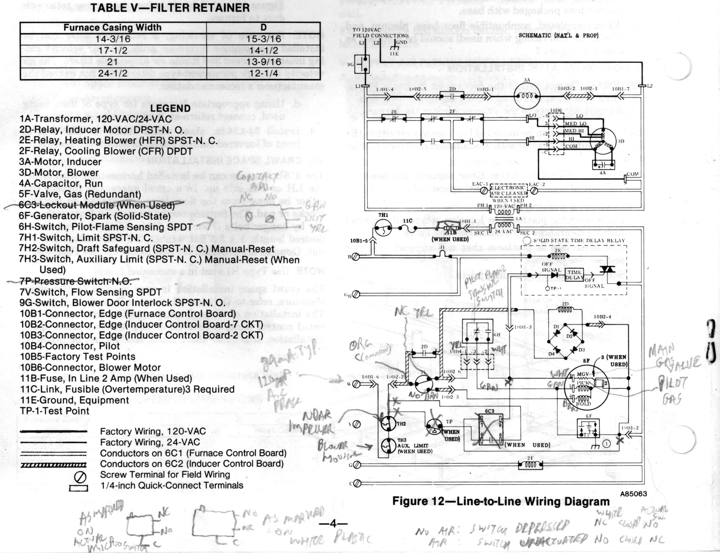
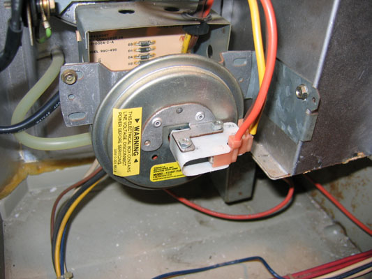
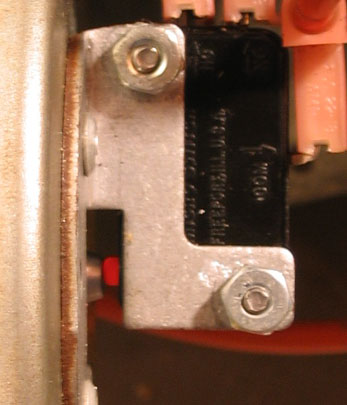
and saw the several switches in line with the gas valve. Ran ’til failure. Did a little tapping with a screwdriver handle: Tapped near the igniter: blips. Tapped near the Draft Safeguard switch (7H2): slightly more blipping. I then noticed the flow sensing switch assembly, and the reliability nemesis of the electrical and electronics world: the microswitch:
One very gentle tap on that microswitch and WHOOMP!… the burners extinguished (while the inducer motor kept running). More tapping there: wild fluctuations between trying to ignite, flames, and no flames/no ignition, all in sync with my tapping (while the Inducer Motor and main blower kept on running). I had my culprit!
This is not the first time nor likely the last that a microswitch has been/will be the nemesis of reliable operation of the device containing it. I could put you all to sleep with stories of microswitch-induced problems i have seen over the years.
Repair, Phase 1
A sane person, especially a pro billing labor time, would probably want to replace the whole Flow Sensing Switch assembly. Being an “electronics guy” and all too familiar with the vagaries of microswitches, i had no interest in paying what i expected would be a good chunk of money for a whole assembly when i knew that just the microswitch was bad… and possibly getting an equally funky microswitch on the new assembly. Oh no… this switch was going to be replaced individually.
There was the matter of the microswitch being riveted onto the flow sensing diaphragm assembly, yet as is usually the case, some careful drilling and tapping got the rivets out with no damage to the microswitch nor the mounting bracket (also riveted to the diaphragm assembly).
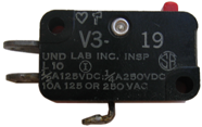
With the microswitch removed, ohmmeter testing did indeed verify that the contacts had their usual funkiness and wildly jumping resistance readings, especially as the actuator button was moved slowly. Hand operation of the switch with my ohmmeter hooked up clearly showed dramatic and wild resistance variations on both the NO and NC contacts, regularly jumping to at least the 100s of ohms, if not higher. Took the switch home and did some research. Turns out that this microswitch is “special” in terms of requiring a very low actuating force of 7-8 g (a.k.a. 69-78 mN, or 0.28 oz.). Otherwise, it is a standard Honeywell Micro Switch brand V3 series, model V3-2414-D9, with the standard dimensions of 27.2 mm L x 15.5 mm H x 10.2 mm Thick, .187" (6.35 x 0.80 mm) Quick-Connect terminals, and electrical ratings of:
5A 125 250/277 VAC
1/10 HP 250 VAC
SPDT
(and L162, for whatever that number may mean… it is not the date code, which i found elsewhere on the switch in standard form)
Days of shopping produced few results, and only mail order/online. Really the only possible options were 3 related items which happen to also be in the Honeywell Micro Switch lineup, though now the V7 series:
- V7-5F17D8: Easy to find, yet too stiff, with a 0.15 N (150 mN) actuating force.
- V7-5F17D8-001-1: Best match, impossible to find. 0.08 N (80 mN) actuating force. No one had any stock, and minimum order quantity was 100 units.
- V7-5F17D8-336: Difficult to find yet available, expensive. 0.02 N (20 mN) actuating force. Would this be too sensitive?
Other than having a 3A rating vs. 5A, these seem to be nearly an exact match for the original. (With a measured peak current draw of 120 mA and average of 84 mA through this microswitch, 3A is plenty!) All feature silver contacts and a temperature range of -40°C to 82°C (-40°F to 180°F). Later, once the furnace was again working, i used my nifty new IR thermometer to measure the microswitch with the furnace all heated up after running for 20+ minutes: 128°F. So, any of these switches should be OK temperature-wise.
Going Cuban
With it being smack dab in the middle of the December holiday season (when obtaining these things is more difficult than usual), the house and my Mom getting colder by the day, and not having the part i really wanted to buy available, i “went all Cuban” on the original microswitch: i repaired it. For anyone who may want to consider this, for any microswitch, i have a separate web page discussing and illustrating disassembly and repair of a V3-type microswitch (and explaining what “went all Cuban” means). The short version for our furnace purposes: Drilled out the rivet holding the switch together, opened it up, cleaned the contacts with my favorite Caig products, tested, repeated the cleaning, tested, reassembled with a nut/bolt in place of the rivet, and final tested: no more jumping, nice steady fraction of an ohm (residual of my meter) resistance on both NC and NO when switched to the respective position. Stayed steady with tapping and with slow actuator movement. Possibly better than new!
In any case, given the poor track record of microswitch reliability (any brand), i highly recommend anyone servicing one of these models give the switch a tap or a few. A small blip on a medium tap is probably normal, yet any blip on a very gentle tap or wild misbehavior on a harder tap seems to me to indicate replacement (or repair).
Troubleshooting, Phase 2
Drove back across town and put in the newly-rebuilt microswitch:
As you can probably guess from the heading for this section, the problem was not solved. In fact, the failure had changed: now the burner flames tended to totally die rather than blipping. Tapping in the vicinity of the microswitch showed that there remained a mechanical sensitivity, even though electrically the microswitch was consistently fine.
Reviewing the schematic (again) reminded me that besides the microswitch, the Inducer Motor Relay could also cause this sort of failure. Took out the relay board, cleaned the relay contacts, and also the edge connector contacts, which were pretty funky. Reassembled… still no joy.
Spent more time studying the Sequence of Operation in the instructions, and carefully monitoring the various circuits, especially what the valve was seeing. The Hold coil was momentarily dropping upon tapping, causing the flames to extinguish and the eventual re-initiation of the startup sequence (with the inducer motor running steady the whole time). Gotta be the microswitch on the flow sensor assembly… but it is electrically OK!
Reassembling the flow sensor with the white plastic shroud around the microswitch left off, i could see that the diaphragm button was still pressing on the switch button when activated with air flow:
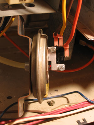
So… either or both the diaphragm unit was failing and/or the microswitch needed to be repositioned farther away from the diaphragm actuation button. More study and experimentation revealed that moving the microswitch away from the diaphragm assembly would provide a more proper lack of switch actuation with air flow, yet still push in the switch sufficiently when there is no air flow.
Repair, Phase 2
I filed slots in the bracket switch mounting holes to allow this adjustment, and reassembled and tested: no more dropouts with light taps! The furnace seemed to be running well!
Before self-congratulations were fully underway, the “blipping” failure returned: the original symptom was back! Sigh…
Troubleshooting, Phase 3
At least now there was no mechanically-induced main burner total dropouts and recycles. There was still mechanically-induced “blipping” when tapping the pilot assembly, and the original symptom. Remember that saying about “When you have a hammer in your hand, everything looks like a nail”? Well, being an Electrical Guy, every failure was leading me to seek an electrical cause.
Repair, Phase 3
Naturally, i removed the pilot assembly, disassembled the Pilot Flame Sensing Switch:
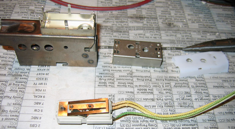 ,
,
tested it (it tested fine… this might have been a clue), cleaned the contacts (they did not really need it), reassembled, reinstalled. Again, at first it seemed like a fix, yet once the furnace was more fully heated up, the blipping resumed.
Troubleshooting, Phase 4
Back to studying the Sequence of Operation and the signals on the gas valve. Everything was now solid except the MGV (Main Gas Valve) line… which came directly off the switch i had just cleaned and tested (pilot flame sensing switch). The feed into that switch was rock-solid.
Having pretty well run out of electrical failure modes, i needed to open up my mind and seek other contributing causes of the failure.
Whomever installed this furnace apparently was not planning to service it: there is an essential structural 2 x 4 directly in front of, and only about 1 cm away from, the Bottom Plate Filler, which is the left-side front end panel as this furnace is installed (horizontally). There was plenty of room to move the whole furnace over about 5" to the right, with no impact on ductwork, venting, gas service, electrical service, nor anything else. Someone was apparently not thinking!
In any case, it made accessing the pilot assembly and getting a good look at the pilot flame unnecessarily and quite difficult. Which may be the reason (along with my “electrical myopia”) that i had not before noticed the following sequence:
- Flame curls away from the Pilot Flame Sensing metal plate.
- Main burners extinguish for a fraction of a second.
- As the burners extinguish, the flame moves back onto the metal sensing plate, restoring the MGV circuit.
I watched this “curl-Blip-curl-Blip” process go on awhile, and concluded that the flame was not consistently keeping the Pilot Flame Sensing Switch fully activated, as it would curl away from the sensing metal plate, yet only when the furnace was fully warmed up!
Repair, Phase 4
It was then that i noticed that, for some reason, the main gas supply to the furnace was only halfway on. Turning the external main valve a bit further on, the curling ceased and with it, the blipping. The main burner flames also became more noisy and intense. Now, this “interesting” valve setting could have been done by an HVAC professional, my (deceased) father, or myself at a prior time, working from least to most likely. I have a very vague memory of maybe turning this valve down on a past visit to the furnace… if so, likely because the flames seem so very noisy and tend to spill past the bounds of what this layperson would expect when the valve is wide open.
As i type this, i am making plans to revisit with a homemade manometer and verify the actual gas pressure, to compare with the nameplate specs and know how best to set that valve. From some preliminary research, it looks like normal full-on will be optimal. In any case, turning up the external main gas supply valve slightly from where it had been was sufficient to stop the flame curling, and hence stop the original “blipping” failure. The incidental cleaning of the microswitch, relay, and relay board contacts did not help the original symptom, yet made the furnace more robust against mechanical shocks from small earthquakes, heavy trucks driving by, and so forth… and generally enhanced reliability.
Followup
Upon revisiting with the homemade manometer, i learned that the slightly more open partially open setting described in the last paragraph had the pressure near or just below the rated minimum of 4.5" W.C. Restoring the supply gas valve to fully wide open provided a level in the middle of the range (i already lost the number i wrote down) of 4.5" W.C. minimum to 13.6" W.C. maximum. The main burners make a whole lot more noise at this setting, which i am not accustomed to hearing, so i expect it was me that mis-adjusted the incoming gas supply and caused this problem.
Executive Summary
Maximum burner flame (thus furnace) reliability may be achieved by attending to the following:- Start by ensuring that all the electrical connector contacts are clean, especially those which attach to the inducer control board. Use an excellent contact cleaner. This step alone may solve a lot of issues.
- With the burners running, very gently tap the microswitch on the back of the Flow Sensing assembly (a.k.a. Pressure Switch assembly). If anything beyond a very brief “blip” occurs, replace the assembly or replace (or go wild and repair) the microswitch.
- With the burners running, gently tap the inducer motor relay. If anything (motor, burners, anything else) “blips” or fails, replace the relay or the board, or at a minimum give the relay contacts a stellar, proper cleaning.
- If the symptoms are valve clicking simultaneous with the main burners “blipping” off momentarily, check that the input gas pressure is within spec, and that the flame is consistently heating the pilot flame sensing assembly. If these points check OK and the problem continues, gently tap the pilot flame sensing assembly during burner operation. Anything other than a very slight blip suggests that replacing the assembly (or disassembling and cleaning the switch contacts) may help.
 World O’ Appliances/Household/Plumbing/Irrigation/HVAC/Hardware