Doug McNutt’s MOSFET Modification for the Breville 800ESXL Espresso Machine
Doug’s Findings and Analysis
Everything on this page below this paragraph and above the footer are Doug McNutt’s own eloquent words, other than a few comments of mine [in brackets like this].
Your posting on the Breville 800ESXL coffee maker is excellent. Without it I probably would have told the owner, my brother in law, to forget about repairing the thing.
Using your take-apart instructions I quickly established that the problem with this one was a failed SCR and nothing more.
With the pump disconnected I experimented with a 1 ohm shunt and an oscilloscope to understand how the internal diode is hooked up. I was a bit surprised to find triangular current waveform repeating on each positive period of the AC power:
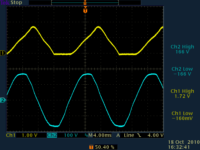
I also looked at the output from pin 8 of the 14 pin DIP. That looks like TTL and it wasn't going all the way to zero in the off state. And the design drive to the SCR is nothing more than a DC level applied to the gate. I expected to see pulses applied synchronously with the AC line. The microprocessor seems to be more of a gate array than a clock-driven stored command computer. I really worry about phase shifted and harmonic currents in the pump coupled with a still slightly positive gate voltage. Is there some way the SCR can be denied its turn-off conditions? Every SCR circuit I have previously seen uses either phase-shifted AC with a diac or pulse transformers to drive the gate. Are SCR's even tested for DC gate drive?
[Yes. At least i’ve seen such on some spec. sheets (e.g. for the Teccor Sensitive SCRs, Thyristor Product Catalog section E5, page E5-4) Igt and Vgt are specified as D.C. values. But i’m far from a thyristor expert!]
It's hard to tell if the pump has a free wheeling diode directly across the coil. It ought to. Interruption of pump current could generate pretty big voltage spikes at the anode of the SCR. But the SCR would already be conducting and it shouldn't be a source of failure.
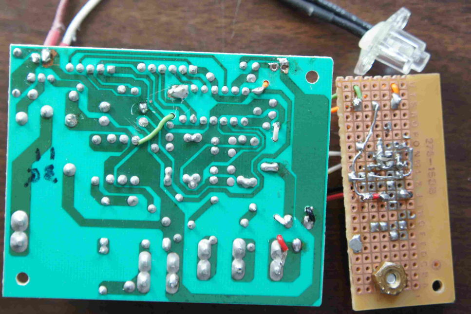
MOSFET Modification
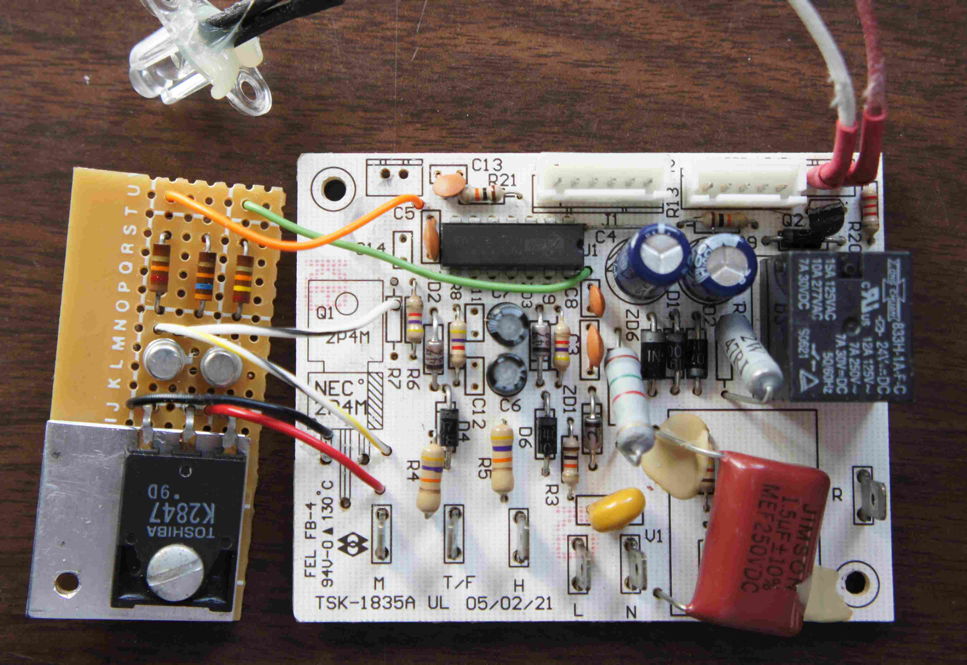
With all of that in mind I looked in my collection of SCR's and found nothing suitable because of the low drive current available. What I did find is a whole bunch of N channel MOSFETS from the likes of old CRT monitors and switching power supplies. The circuitry has 27 volts available and it's a simple matter to amplify the signal from pin 8 so that it can turn on a MOSFET. That doesn't have any timing problems associated with turning off an SCR. It makes wonder why the original designer used an SCR in the first place.
[Parts count. I can nearly guarantee it: 2 resistors + 1 SCR for the factory version vs. 4 resistors + 2 bipolar junction transistors + 1 MOSFET transistor for the MOSFET modification. And/or the designer’s lack of familiarity with the vagaries of SCRs.]
I set up a circuit and had some fun testing it. No water on the test bench and my isolation transformer wasn't big enough to turn the heater on. Grounding the hot side of the power plug to the oscilloscope takes some guts but it's the only way to measure voltages on the circuit board. Why did they label the L and C wires that way?
[No idea. Pico Electronics Ltd., the company that originally designed the X10 powerline remote control family of devices, did the same thing. Anyone know why?]
The solution:
- Remove power to the heater by disconnecting the power at the R terminal on the circuit board.
- Fake out the test for "I'm hot" by disconnecting the H terminal. Leave the T/R heater terminal connected.
- Don't worry about connecting the pair of leads from the microswitch on the right side of the rotary valve/switch.
- Apply line power with the rotary valve centered.
- Poke the power button.
- Select "hot water" with the button for it on the right side.
- Rotate the valve to the left. The pump should start.
Actually the pump runs for a few seconds when the power button is initially pressed. The lady tells me that the Gaggia we use here does something like that too. Perhaps it's to be sure there's some water in the tank.
[I think it’s to prime the pump, especially since there’s no water sensing as far as i can tell, at least on the 800ESXL.]
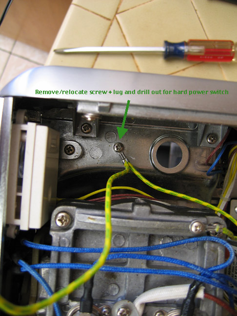
“Hard” Power Switch Modification
On the left side there is a ground screw that occupies a place for a power switch that would fit, facing down, on the operator side of the left tube that holds the top in place after re-assembly. I found a 10 amp toggle switch and drilled out a 15/32 hole for it using the ground screw hole as a starting point. It was easy to find another screw for the ground and I extended the power wire a bit to hook up the switch on the hot side of the power wire.
Return to the main Electrical/Electronic Issues - Breville 800ESXL Repair article
 World O’ Appliances/Household/Plumbing/Irrigation/HVAC/Hardware