- Breville 800 Repair Home
- Normal Sequence of Operations
- Disassembly
- Electrical/Electronic Issues
- Mechanical/Water/Hydraulic Issues
- Modifications
Electrical & Electronic Repair Notes for the Breville 800ESXL Espresso Machine
I expect most of you know well what you’re getting into and are well aware of everything mentioned in the following warning, yet since that may not apply to everyone who passes through….
 IMPORTANT: This information is provided AS-IS, for informational purposes only, with no warranty whatsoever. Neither Sonic Purity nor anyone at Siber-Sonic.com can control your ability to successfully and safely utilize this information, and we accept no responsibility for anyone’s actions (beyond our own) related to the content of this website. This equipment utilizes the A.C. power line, which is dangerous. Do not attempt any of these electrical repairs if you have any doubt about your ability to work safely with household powerline-operated devices. It is your responsibility to know and understand common safety procedures, especially those involving electricity at potentially dangerous power levels!
Index
of topics covered on this pageGeneral Information: Essential Reading Prior to Any Electrical/Electronic Work
- Production Changes and Schematic Differences—Important Warning
- Disconnecting Wires? Document Them!
- Links to Parts are Examples
- Pump Motor Runs When Unit is Off tl;dr: SCR breakdown degradation
- Pump Motor Runs Continuously with No Pulsing tl;dr: SCR breakdown degradation
- Pump Motor Runs Continuously with Normal Cycle Pulsing tl;dr: function knob microswitch contacts
- Pump Does Not Run and/or Power LED Flashes When Pressed Then Goes Out tl;dr: open pump circuit
- Heating Element Runs When Unit is Off tl;dr: shorted relay contacts or shorted Q2 etc.
- No Power: Dead tl;dr: power switch or ZD6 most often. ZD6 replacement information.
- Intermittent Operation: Difficult to turn machine On or Off. tl;dr: power switch. Power switch replacement information.
- Intermittent Operation: Pump Fails when Heater On. White LEDs Dim. tl;dr: V++, esp. C1
- Intermittent Operation: Pump Fails during brewing. White LEDs blink: Dim/Bright. tl;dr: V++, esp. C1. C1 replacement information.
- Intermittent Operation: No Pump, No Heat. tl;dr: V++, esp. C1
- Relay Buzzes tl;dr: V++: C1, C2, fractured SJs
- Intermittent Operation: Intermittent heating. LEDs flicker randomly tl;dr: fractured solder joints
- Any Other Electrically-related Problem: Check Power Supplies tl;dr: usually V++ and C1/C2/ZD6
- Intermittent or Permanent No Heat tl;dr: various, tank LED out. Q2 replacement information.
- Intermittent or Permanent Weak/Low Heat: Warm but not Hot Water tl;dr: overheated connections, thermostat
- Intermittent or Permanent Lack of Steam from Wand (liquid water instead) tl;dr: left microswitch
- Cannot select Steam after having selected Hot Water tl;dr: disc cap front board
- Soldered pins pulled out of printed circuit board
- Not A Troubleshooter? In a hurry?: Throw Parts At The Problem
- Easy, Expensive Repair: Replace The Circuit Board
General Information
General Information: Production Changes and Schematic Differences
IMPORTANT: Different machines have different circuits! There were major circuit changes during the many years’ production run of the Breville 800 series espresso machines, as well as differences between products for different markets around the world. For the safety of yourself and your espresso machine, please verify that your machine’s actual wiring and circuitry matches the schematic you’re using.
In the summer of 2011, a kind reader provided me (and us all) with what appears to be the service manual for the Breville 800 series of machines, as of early 2008. There is enough to say about it that i discuss it on the separate Breville 800 Series Service Manual page (including prominent differences between my schematic and the one in the service manual, and what [little] is known about production changes).
The service manual is dated 19 February 2008, which i used to ASSume meant it had a newer schematic. The situation is a lot more complicated than that, detailed on the Service Manual page. Years before 2011, i drew up my own schematic, presented below. The 800ESXL here was received as a gift for Christmas 2006 and appears to have a 637 date code, which would mean the machine was manufactured during the 37th. week of 2006, which i used to think was an early(-ier) production model, but as of late 2025 now conclude was later production. What little is known so far about production changes is also on the Service Manual page. It is up to each Breville 800-series machine owner to confirm which—if either—of the schematics applies.
Having no documentation of production changes, knowing the production date code is useful mainly as a sweeping generalization guide. Information on locating and decoding the production date code for the model 800 is on this article’s home page. Again, tracing the wiring of the machine in front of you and matching it to the drawn schematic below or one of the revisions discussed on the Service Manual page is essential, and far more relevant than the date code.
General Information: Disconnecting Wires? Document Them!
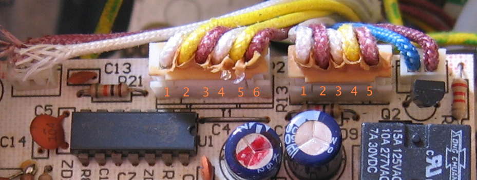
Apparently Breville found that wires with high-temperature insulation are expensive: they only used 3 colors in the model 800: brown, blue, and a few red that can look brown depending on one’s color vision and lighting. Because of this, multiple blue and brown wires connect to the printed circuit board (PCB). Once disconnected, it is not possible to know which wire goes where solely by color: one has to trace the wire back to its other end, find that part on the schematic, find to which letter contact that wire connects on the PCB, then find that letter on the physical PCB and reconnect it.
I’ve found it easier to tag each wire with some sort of stick-on label or similar, marked with the letter of the connection point on the PCB. I recommend you do the same, or whatever other alternative wire position documentation works for you.
But what if you didn’t heed this warning? Or received a machine where someone before you disconnected the wires?—and you don’t read schematics? This page on Breville 800 series Espresso Machine Wiring might possibly help (and is going to repeat what i just wrote here).
General Information: Links to Parts are Examples
In an attempt to be helpful to those who have little to no experience ordering electronic parts, for many years this page of this article has offered links to specific parts from at least one parts vendor i often use (no business relation; no affilate links etc. Shop wherever you want). At the time i first found these part links and put them in the article, the parts were readily available in stock for purchase in single-unit quantities. This article is now beyond a decade and a half old… parts go in and out of stock, websites change (and all too often companies don’t provide workable link redirects). Therefore:
- Some links may be broken
- Some links may still work, but show the part as No Longer Available, on backorder, or only available in large quantities
In some cases—at least for Digi-Key—the site may offer links to substitute parts. Chances are good that the substitutes will be close enough for a Breville 800 series espresso machine circuit, but unfortunately the onus is on the buyer to evaluate. This page is intended primarily for those with electronics skills and experience able to identify and purchase correct replacement parts on their own, and those currently lacking those skills motivated enough to consult outside sources to learn how, or for help. If links to parts no longer work or show the part is no longer available for single piece purchasing from stock, no substitutions are offered, and you Just Cannot find a substitute yourself, as my time/schedule/life permits, i’ll consider looking into revised options if you’ll point me to the part(s) link(s) in question.
Failures and Repairs
Failure and Repair: Pump Motor Runs When Unit is Off
This is a fun one… you’re sitting there at home, possibly reading something in your seat on the Comfy Couch as i was, and all of a sudden you hear a familiar buzz. Then it stops (maybe… maybe not). Later, it comes back. You investigate, find it is coming from the kitchen, and indeed from the Breville 800ESXL. But… the front panel of the Breville is dark: it is Off. Like many modern electrical/electronic products, the 800ESXL has a “soft” (logic controlling) power switch rather than the “hard” (removes all electricity from the device) power switches of decades past, so this failure is all too possible! (I feel very fortunate to have been at home, rather than having no one home, possibly on vacation, and the pump grinding away for hours, days, or weeks… probably cycling on and off thanks to its thermal breaker.) One can certainly add a “hard” power switch, and Doug McNutt has suggestions for a convenient mechanical arrangement.
The failure just described—the pump running when the machine is plugged in yet powered off—is the specific type of failure covered in this section. If the pump on your machine is running when it is not supposed to, but only when the 800-series espresso machine is On, check the next two sections: Continuously On, Keeps running but does pulse.
By now it is (might be) running continuously, so you quickly unplug it and get to work, starting with the disassembly described on the previous page. Let’s have a look at the schematic for a North America 120VAC unit:

Looks like the possible failure modes are:
- Q1 conducting (turning On) without being signaled to do so.
- R7 opening and the gate of Q1 not being pulled down to common reliably/sufficiently.
- P62 (pin 8) of the microprocessor IC signaling Q1 to conduct when it ought not to be doing so… perhaps because the power supply to the IC is out of acceptable tolerances.
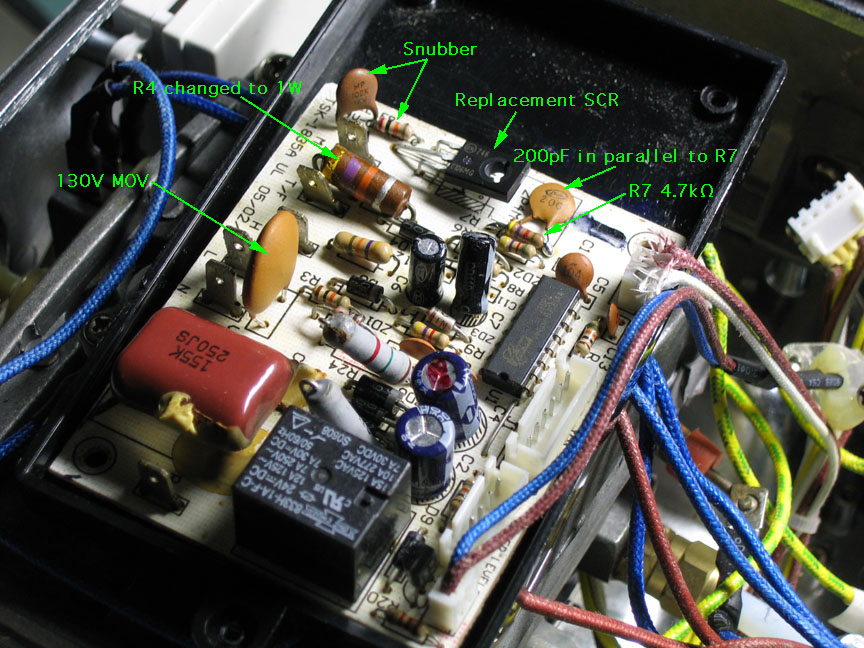
By all means, start with the obvious: anything visually “wrong”. Well before i threw away a day of my life drawing out the schematic for the unit[1], i saw some problems, and repaired them. They’re discussed further below, as they turned out to be unrelated to this failure, though still worth the time to address.
After some false hopes in early 2009, extensive testing and research in Fall 2009 revealed that, without question, the first option above was the failure mode for the unit here (and probably nearly all 800ESXL units with this symptom): the SCR (Q1) was conducting without being instructed to do so. (Could this have anything to do with the 2P4M being made by Jilai, whom i’ve never heard of, instead of NEC?)
Troubleshooting Conclusions, Analysis, Research, and Findings
Not interested? Skip ahead to the actual Repair.Troubleshooting
After verifying that, yes indeed, R7 was intact, the correct value, and working, the next troubleshooting step was looking at the sillyscope waveform of the SCR’s gate-to-cathode junction (across R7) with the unit failing and working:
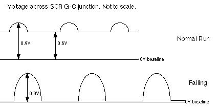
During failure, the 60 Hz half wave humps drop from their approximately 1V peak to (or very close to) the 0V baseline. During normal operation, the drop only goes to 0.6V, or there may be almost no visible humps nor drop at all (this latter condition is more likely with a good SCR in place). Clearly, the failure was happening close to this observation point.
Next, i placed a voltmeter (set to D.C.) across R6, to effectively measure the current into (or, if failing, out of) the SCR gate:
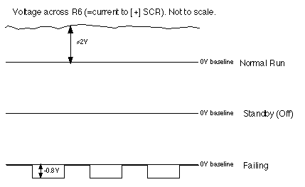
Here came the smoking gun: During normal operation pump running conditions, current flow was from the IC into the gate of Q1. During failure, the current flow was very clearly from the gate of Q1 into pin 8 of the IC, which is not ever supposed to normally happen!
To further nail down the bad SCR diagnosis as being definitive, i disconnected one end of R6, so that Q1 was entirely isolated from the IC: the IC had no way to control Q1. In this condition, Q1 should remain forever Off. The Breville failed in exactly the same way as when R6 was attached, totally eliminating everything except Q1 and R7. Yet R7 was already found to be just fine, so that left only the NEC 2P4M SCR, Q1.
Analysis and Research
At this point, many people might go ahead and replace Q1 and be done with it (or so they think). I wanted to know Why: Why did Q1 fail? This led me into doing a lot of research on thyristors (especially SCRs) and their failure modes.
I learned quickly that thyristors turning themselves On spontaneously is a fairly common problem. To make a very long story very short, there are many causes for this, and which cures to implement depend upon the nature of the cause(s) in a particular circuit.
Lower the Gate-to-Cathode Resistance
Most SCRs have 1kΩ of resistance or less between their gate and cathode, primarily to minimize unwanted turn-ons due to circumstances such as the voltage across them rising too quickly (dV/dt turn-on). The Breville engineers of necessity chose a “sensitive gate” SCR, which can be driven directly by the low power output of a microprocessor IC pin. My calculations verified that 1kΩ would be too low to reliably work this circuit. Yet 10kΩ comes out as excessively high. The literature makes clear that a lower gate to cathode impedance leads to less chance of (unwanted) dV/dt turn-ons.
The 2P4M and most other sensitive gate SCRs with similar ratings require a minimum of 0.8VDC gate voltage to turn On into conduction mode, at at least 200µA gate current. The Elan microprocessor IC nominally outputs 5VDC, which drops to about 4.2VDC @ 5mA, which is about as much current as one ought to draw from this IC (allowing for a safety margin). The existing circuit supplies roughly 1 mA of current to Q1, at about 3.4V. Experimenting with different resistor values for R6 and R7 led me to conclude that a safe alteration to lessen the chance of Q1 spontaneously turning On would be leaving R6 at 4.7kΩ and cutting R7 approximately in half, to 4.7kΩ. The current into Q1 would remain roughly the same (and well above the 200µA minimum) and the voltage would be about 2.5V, still well above the 0.8V worst-case minimum turn-on voltage. I have no idea why the Breville engineers did not choose this value (or something close) for R7.
Further Lower the Gate-to-Cathode Impedance with a Capacitor
Lowering the gate resistance is good; adding some capacitance to slightly slow down the turn-on is better. The Breville engineers may have had some thoughts along these lines due to their inclusion of holes and traces for the un-stuffed C14 capacitor. Yet from my reading, a capacitor there would be vastly less effective at minimizing dV/dt activations than one directly across the gate-cathode junction (e.g. parallel with R7).
First, i had to be sure that any slower turn-on from added capacitance would be a magnitude or more less than the pulse width used by Breville to pulse the pump in some modes. The measured pulse width on the unit here came out to 17.5 mSec. By this criterion, 1 mSec or lower should be fine. Yet ON Semiconductor publication HBD855 recommends the gate turn-on current have a pulse rise time of less than one microsecond (µsec) and a pulse width greater than 10 µsec. No problem with the width, yet the rise time goal would need to be lowered to 1 µsec. or below. 1 µsec./4.7kΩ≈210pF, so i chose a 200pF capacitor to add in parallel across R7.
Add a Snubber
Another interesting design choice of the Breville design team was omitting a snubber network across the anode to cathode junction of Q1. Consisting of a series resistance and capacitance, the snubber component values are selected to counteract the effects of an inductive load, such as the Ulka pump used in the 800ESXL. Snubbers can further decrease dV/dt unwanted turn-on, and also somewhat diminish the effects of powerline surge pulses that would otherwise stress Q1.
While i do have an EE degree, i lack experience designing snubber networks, and for many years (actually, decades) have been curious at how component values for them have been chosen. What i could find online led to 3 basic categories of approaches:
- Close enough: use 0.1µF and 100Ω
- Calculate what is needed from the characteristics of the load
- Measure what is best with the actual circuit
I chose the middle method. Making things more exciting is the fact that the Ulka pump unit contains an internal rectifier diode, so even though it is marked A.C., it operates with half-wave D.C. power. This explains why Breville is using a single SCR to control the pump. It also makes it more difficult to directly measure the inductance (say, with my nifty early 20th. century General Radio impedance bridge). Trying to think of a way to bias On the diode and simultaneously measure the inductance made my head spin, so i went for an indirect method: measured the current draw at 120V and did the math.
I measured a reactance, XL, of 120V/0.57A(AC)=211Ω. With the equation XL=2πfL=377L (for 60Hz), L=211/377=0.56H=560mH. Using equations found on or near p. 163 of the aforementioned ON Semiconductor HBD855 document, i somehow (my notes are incomplete) concluded that ω0=29400. C=1/ω02L≈2nF (known to old-timey people as .002µF, or even .002mfd). I chose a damping factor ρ=0.6, so Rs=2ρ√(L/C)=1.2√(.56/2.07x10-9)=19.7kΩ≈20kΩ. And thus came about the values i’m using for the added-on snubber network.
Findings
Even with all these added-on measures to reduce spontaneous turn-on, the existing SCR continued to fail. Why would this be?
From my extensive reading, apparently power spikes exceeding the SCR rating can degrade the SCR hold-off voltage (voltage across the anode-cathode junction which the SCR can effectively block) over time. In other words, as power spikes continue to whack the SCR, it gradually takes lower and lower spikes to actually turn On the SCR via the overvoltage instead of the gate lead.
In theory, the MOV V1 ought to be eating powerline spikes before they get to Q1. Yet was this happening? The NEC 2P4M is rated at holding off 400V repetitive voltage peaks, and 500V non-repetitive peaks. The TVR 07471 MOV is rated to start whacking transients nominally around 470V, with an 8/20µsec. maximum clamping voltage rating of 775V. Hmmm… anyone else notice a problem here? Seems to me Breville either needed to specify the 2P6M 600V SCR, or use a lower voltage MOV in their North American 120V units (MOVs with a lower clamp voltage than the existing device would likely be unsuitable for worldwide power sources up to 240V nominal, and actual voltages sometimes higher than that). This mismatch in abilities is likely why we see so many apparent SCR failures. Here i am guessing that the many intermittent pump spontaneous turn-on events i’ve read about in researching this issue with the unit here are also caused by diminished Q1 hold-off abilities, to the point where normal power line transients exceed the reduced hold-off threshold and activate the pump for a moment or quite awhile.
Alternative Analysis and Research
Doug McNutt has contributed his wisdom and shared his own analysis and a different, elegant repair solution, which i present in his own words on a separate page.
Repair
Change the SCR: The Minimum Required Fix
At a minimum, SCR Q1 needs to be replaced. Especially if no circuit modifications are made, seek out the highest voltage sensitive gate SCR that you can find. I used an ON Semiconductor C106M, rated at 4A 600V. While the case style is different, this device is a solid improvement over the stock 2P4M 2A 400V device. I’m banking on the fact that no added heatsink will be needed, despite the smaller exposed metal area of the TO-225AA case of the C106 family vs. the 2P4M (if this proves to be a bad assumption and the replacement SCR fails in the unit here, i’ll update this paragraph).
Drop the MOV Clamp Voltage (if your circumstances allow)
For those of us living where there is 120V or 100V nominal A.C. line voltage, the next mod is changing MOV V1 to a more suitable choice for our lower line voltage. I happen to have a bag of decades-old VZC130 devices from Thomson-CSF, with a 130VAC (200V clamp) nominal rating. Something along these lines, 130 to 140 VAC nominal and able to handle at least 30 Joules and physically fit should provide a nice improvement. Those living in 220V or higher nominal A.C. voltage areas should leave the existing MOV in place, or if there is any concern that it may have worn out (which does happen over time as a MOV eats voltage spikes), replace with a device with the same or very close nominal voltage rating.
Lower the Gate Impedance
Even with a nifty new SCR and perhaps a lower threshold MOV, why let wild dV/dt pulses that may slip through make the pump run? Change R7 from 10kΩ to 4.7kΩ (still 1/4W) and add about 200pF of capacitance in parallel. Barring catastrophic failure, the voltage here is not going to exceed 5V, so it does not take a large capacitor to get this job done. I used a low voltage (probably 25V) disc capacitor i happened to have. I recommend doing both of these changes, yet if you insist on only doing one, change R7.
Add a Snubber
To further eat any transient pulses that make their way to the SCR, add a series 2nF and 20kΩ snubber network across the SCR (anode to cathode). There should be little enough energy that 1/4 watt should be OK (that’s what i used). There could be a significantly high transient voltage across this network, so i’d go for at least a 500V capacitor. I happened to have a 1nF 1kV disc capacitor that was also small, so it went in the unit here.
All Together, With Feeling
Here’s a revised schematic fragment, showing the changes (in red, where available):
If, like me and my Love (who is the actual coffee drinker and owner of the Breville), you’d rather spend your time making and drinking nice beverages than tinkering inside your espresso machine, i suggest making all the mods above (well, all that you can, depending upon your nominal line voltage). It might be overkill, yet with the continually degrading quality of powerline power in many parts of the world (by which i mean more frequent and/or higher amplitude spikes), it may be necessary to keep the new SCR happy and the pump running only when explicitly commanded to run.
For those keeping track, this set of modifications has continued working without failure all the way from Spring 2009 to the modification date at the top of this article ![]() .
.
Failure and Repair: Pump Motor Runs Continuously with No Pulsing
If your machine’s pump is running when it is not supposed to, all the time or in odd patterns which may be intermittent, this section likely applies to your situation. If instead the pump follows one of the normal run—pulse cycles described in the Normal Sequence of Operations section, then instead you should read the section below: Pump Motor Runs Continuously with Normal Cycle Pulsing.
There are several different causes for the symptom of the pump running when it’s not supposed to run. The key point for this section and the one above is that there is either randomness in when the pump runs, or it flat-out runs continuously and never pulses.
If your machine’s pump ever runs even once with the machine’s power off, the section above—Pump Motor Runs When Unit is Off—applies to you. If your machine’s pump mis-operates only when the unit is On and is either a bizarre random pattern of pumping when it’s not supposed to, or pumps continuously all the time with no pulsing, this section applies.
Here’s the thing: This is the same failure as Pump Motor Runs When Unit is Off! The difference is that there may exist some machines with a production change such that the SCR does not receive mains power unless the unit is turned on. Those of you who are electronics-schematic-literate will readily see that on my schematic there is power to the SCR at all times, and on Breville’s official schematic in the service manual (which may or may not have actually entered production as drawn), the SCR receives its power through the relay contacts. The bottom line is that the troubleshooting and repair procedure is the same as for Pump Motor Runs When Unit is Off, above. Follow that section, being sure to use the correct schematic diagram for your unit!
Failure and Repair: Pump Motor Runs Continuously with Normal Cycle Pulsing
This section applies if:- The pump only runs when the machine’s power is On
- The pump follows the normal run—pulse sequence for either espresso or steam wand mode
- The pump keeps running, as if the function knob were left in Brew Head or Steam Wand position all the time
The key here is the normal pulsing cycle. This tells us that the IC has control of the SCR—the SCR is not randomly going off, nor is it shorted. In the two sections above where the SCR itself failed, the IC has no control of the SCR. It might not always be possible to distinguish between these failure modes, so you may have to try both what is in this section and those above.
So far and until further notice, i have yet to receive a report of the IC itself failing. Thus if the IC is able to control the SCR and the pump is running at improper times, we need to look at the input signals to the IC. Far and away the most likely source of problems are the two microswitches on the function knob assembly. The knob itself controls the hydraulics: where the water flows:
- Through the brew head in the Brew Head position
- Into the overflow tray in Standby
- Through the steam wand in Steam Wand position
The switches are needed to convey function knob mode information to the IC. The schematic references differ between my schematic and Breville’s, and frankly, i think mine are clearer, so let’s use those for the purposes of this explanation.
- In Standby, mains power flows through the common (C) and Normally Closed (NC) contacts of S2, sending a high signal to the T/F terminal.
- In Brew Head mode, this switch remains in this position, and additionally S1 closes, telling the IC to pump.
- In Steam Wand mode, S2 switches from NC to Normally Open (NO). The T/F signal goes low, and i believe S1 is open so P64 (on my circuit) is high, as it is for Standby.
If any of these switch signals are incorrect, the IC may activate the SCR and operate the pump on one of the water-flow cycles at inappropriate times. For one example, let’s say that S2 fails such that it goes high resistance or open circuit between C and NC. If this happens, the IC will think it is in steam wand mode, and the pump should keep pulsing. Second example: if instead there is a short in S1 or C13 or the wiring to S1, the IC will think that S1 is closed and that it should run the pump in brew head mode, no matter which position the function knob is in.
There are likely other combinations of failures. The thing for you to do is ensure that the proper high/low signals are being sent to the IC, following your machine’s schematic, for each function knob position.
Failure and Repair: Pump Does Not Run and/or Power LED Flashes When Pressed Then Goes Out
Kindly contributed by Mike, in his words with minor style editing.I bought my Breville 800 second hand (Australia) in what I thought was great condition. It worked for about 3 months but did leak a lot of water from behind the brew head. I put up with it until yesterday when suddenly the machine would not stay on. More accurately when the “Power” button was pressed the LEDs would flash then go out. I opened the machine and first thing I discovered was the drain hose from the heater block to the bottom reservoir was disconnected from the fitting on the heater block. This was the reason for so much water dripping from behind the brew head. I suspected this may have had some bearing on the problem and began checking the electronics which I suspected may have been affected by the steam and water being released inside the machine. All supply voltages checked out OK even when I cycled the power. By chance I measured the pump continuity and found it was open circuit. Take note here that as you pointed out the pump has an internal diode in circuit so before assuming you have an open circuit pump be sure to reverse the polarity of your DVM. A good pump will only show continuity in one direction due to the diode. I believe the diode is there to slow the cycling of the pump to half the mains frequency. I looked on the internet for a new pump and found the price and sources prohibitive for repair. In my garage of treasures I did have an old Sunbeam EM3600 coffee machine which died in the characteristic way for this model with a cracked brew head. I checked out the pump and it was an identical wattage (47W) and looked similar. I hooked it up to 240V with a couple of tubes to check whether it was still working after sitting so long. Disappointingly it didn’t pump water despite running. When I pulled the plastic pump mechanism apart I found it very corroded. Not to give up I thought why not fit the relatively new plastic pump insert from the open circuit pump into the working solenoid of the corroded pump? It wasn’t easy but I was able to prise open the metal casing of the Breville pump and remove the plastic pump mechanism which I then fitted to the Sunbeam solenoid. I bench tested it and it worked fine. I installed it in the machine and now we’re drinking coffee again. Note when fitting pump: if it doesn’t run try reversing connections to it as the conducting SCR in the electronics board and the diode in the pump makes the pump polarity sensitive.
As an experiment I disconnected one lead of the pump to see if it simulated the momentary flash of the LEDs, surprisingly it didn’t. It simply sat there powered on without the pump running. Time prevented me checking further to see if the hot heater block had changed some kind of interlock to change the fault appearance. Bottom line if you have a momentary flash of the LEDs or the machine powers on and the pump doesn’t run look for an open circuit pump. If you can lay your hands on a similar pump from a different machine chances are you can fit it.
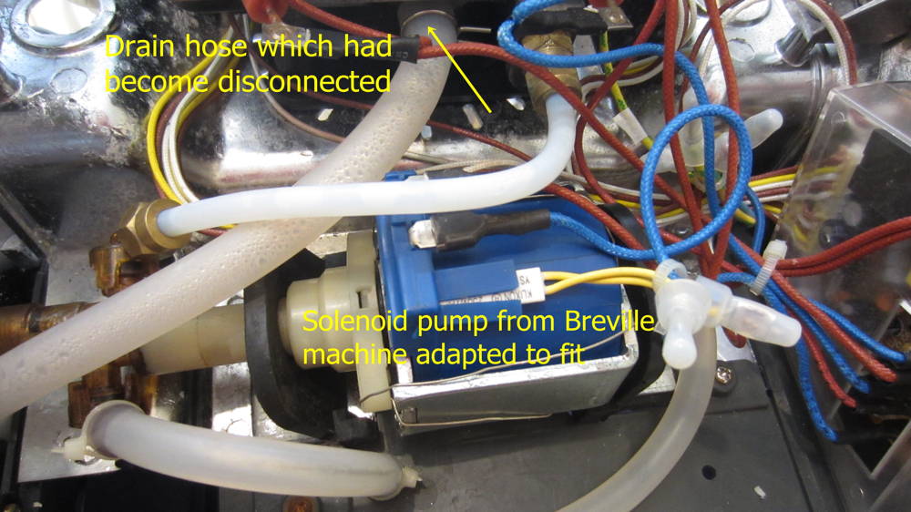
I believe the caption was meant to read: Solenoid pump from Sunbeam machine adapted to fit
Failure and Repair: Heating Element Runs When Unit is Off
This one’s fun. The machine appears to be off: none of the white LEDs are lit—neither the big round button surrounds nor the water tank illuminator. The unit looks off, and indeed it is off. But the thermal block is definitely hot, and one can see the red Heat LED cycling normally. If the knob of the machine is turned to Steam, the red LED lights continuously and the thermal block heats to the higher steam temperature. How can this be?
Relay RL1’s contacts may be shorted
The easiest failure and thus the most likely is that the contacts of relay RL1 have welded themselves closed, such that they are completing the circuit to the heating element even when the relay coil is not being activated, such as when the machine is off. Note that this can be a permanent or intermittent failure. If the relay in your model 800 has ever been buzzing, this is an especially likely failure mode.
To test for this failure, unplug the espresso machine, disassemble it, and measure the resistance across the contacts of RL1. It should be a very high resistance, or an open circuit. If it reads a low resistance, say anything under 1kΩ (and probably well under 100Ω and quite possibly under 10Ω), the relay has failed, and needs to be replaced. If the problem is intermittent, you may need to carefully run the machine all opened up until it fails, then unplug it and carefully re-measure the resistance of the relay contacts. Here’s how Louis-Martin A. of Montreal described the intermittent failure on his:
I did some measurements on RL1 pins and, as you expected, the problem was there. At a cold temperature and with some taps on the relay, the circuit is open. When I plug the unit, the heating circuit stays off.
Things start to get funny once the machine is turned on. It seems that once warmed up, the relay contacts are stuck closed and stay in that state when the unit is powered off. Only if I tap on the relay, once the machine is unplugged, do I get an almost open circuit. My analog meter’s needle is pointing a very high resistance. Almost infinite but not quite much.
Louis-Martin later wrote to confirm that replacing RL1 resolved this problem. As of November 2017, a second report of RL1’s contacts being shorted and replacing RL1 solving the problem came in from site correspondent Soroush, also coincidentally of Montreal, Canada.
Theoretical long shot: Power LED is out and Q2 is shorted
This is a theoretically possible failure which has never been reported. It is only possible if the Power LED never illuminates. If it does, this theoretical failure is not possible. If that LED has failed and Q2 has shorted, then RL1 is on when it is not supposed to be through no fault of its own. Important: this only applies to models where the Power LED is connected to the emitter of Q2… if any such machines were actually manufactured. In known production units where the water tank LED is in this position, it is that LED which would have to be failing with Q2 also being shorted.
This theoretical failure is being mentioned only for completeness, since it is possible. It is far, far, far more likely that RL1 has failed.
Failure and Repair: No Power: Dead
Though not a problem (so far) on this particular unit, there have been quite a few reports of dead 800ESXLs: no signs of power.
Start with the Easy: Test the Power Switch
With the unit unplugged, measure the resistance across the power pushbutton. It should be very high under normal circumstances, and very low when depressed. How low? Well, ideally 0 ohms. 1Ω or less is good. Up to 5Ω may be OK. If it’s 10Ω or higher, it’s worth working on it or replacing it. More information on the switch and replacement in the section below: Intermittent Operation: Difficult to turn machine On or Off. Sometimes difficult includes extremely difficult, like not at all.
Thanks to site correspondent Joseph S. for this tip/reminder. He notes that in his unit he needed to replace both the Steam and Hot Water pushbutton switches on a previous repair. For at least some production runs with certain switch batches, it may be that the “tact” switches are a weak point, worthy of scrutiny.
Move On with the More Challenging
Several reports mention zener diode ZD6 overheating or outright failing. This is the front-line primary voltage regulation device for the machine. For reference, here are characteristics of the two main power supply voltages, which i refer to as V++ and V+, on our unit when it is working properly:
| Voltage | Ripple | |
|---|---|---|
| V++ | 28 VDC | 1.8 VACp-p |
| V+ | 5 VDC | <30 mVACp-p |
Note that our unit uses a 1N5935B 27V 3W 5% zener diode for ZD6. Others have reported ZD6 being a 1N4749A 24V 1W 5% zener diode. The 1N5935B appears to be a production improvement (3W vs. 1W), and i would recommend it over the 1N4749A for replacement. The exact voltage is not critical in this part of the circuit, as it only drives the relay and tank illumination LED. Not sure why the Breville engineers decided to go with 27V, yet i trust them. Our ZD6 has 13 mA flowing through it, for a power dissipation of .36 W. One would think a 1W zener would be OK in this application, yet 3W definitely provides a larger margin of safety, and in this series of diodes, in the same case size.
Some people who posted on other sites (e.g. FixYa.com) seemed to confuse one person’s report of a good ZD6 having .46V across it with the actual zener voltage. That person seems to have been discussing the normal forward voltage drop across ZD6 (out of the circuit, i assume) using the diode test mode of a typical multimeter. The best test is really measuring the voltage across ZD6 in-circuit, ideally while varying the incoming voltage to the machine with something such as a variable autotransformer (Variac®, Powerstat®, etc.): if the voltage stays nearly constant (changes of 10s to low 100s of millivolts OK) with varying input line voltage and remains within the specification for the particular diode (25.6 to 28.4V for the 1N5935B, and probably 22.8 to 25.2V for the 1N4749A), the diode is OK. As usual, a shorted ZD6 would have nearly no voltage across it, while an open ZD6 would have far, far over 27V across it. If one wants to perform the usual diode test, expect the usual silicon diode result: .4 to .7V (.6 on my Fluke 77 with our particular ZD6) forward-biased, and open circuit (infinite) reverse-biased.
Finding a Replacement ZD6
I’ve received several emails wondering where to get a 1N5935B in small quantities. Apparently, this is not easy, since this is apparently not a popular part. Fortunately, the circuit is not so critical that this exact part (nor an exact substitute) is required.
We already know that the Breville engineers were not concerned with changing the voltage from 24V to 27V, so any zener voltage in this range is OK. The usual safety factor is doubling, so with a power dissipation around .36W, doubled to .72W, in theory any diode able to dissipate 1W or greater should be sufficient. It appears that Breville moved from 1W to 3W in later production, so preferably a 3W or greater power dissipation rating will apply to the replacement diode… yet 2W may very well live a long, productive life. 1W and 5W are the standard zener diode wattages, and most easily found diodes will have one of those two ratings. 5W is just fine, other than being physically larger, especially in terms of the lead wires. It may be necessary to drill the holes in the PCB to accept the wider lead diameter of 5W devices. Both the diodes used by Breville have tolerances of 5%, so we should stick with that (or use a tighter tolerance… 4% down to 1%).
So, in summary, we need a zener diode with the following characteristics:- Zener voltage between 24V and 27V
- Ideal wattage rating 3W, yet anything between 2W to 5W should be just fine. Even 1W may be OK
- Tolerance 5% or tighter (e.g. lower percentage number)
- Physical package: Axial (tubular body with wires coming out each end). The exact package number does not matter, unless you wish to correlate it with lead diameter. Surface mount won’t work (at least not easily).
Now, go to your favorite electronic parts vendor. I like Digi-Key, so for this example i searched on their site, plugging in the parameters above (details omitted… it will vary with different companies’ websites). On 14 June 2010 around 6 PM PDT, limiting the results to items in stock, i got 13 results. Three of these had minimum order quantities much greater than one, so really 10 usable results. I then scanned the results for power rating, and found one 3W diode:
- 1N5934BG 24V 3W 5%
This is the direct relative of the 1N5935B in the 800ESXL here. It should work very well—every bit as well as the 1N5935B. It is quite possible that Breville used the 27V diode because they could get it in quantity for a lower price… these things are huge consideration for “consumer” goods, to keep them affordably priced.
My next choice would be one of the 5W options:
Note that the actual suffix varies: some of these are BG, some are BRLG. I’m so unconcerned with the details of these differences that i did not even look them up. The primary electrical specs (including some not retyped here) match exactly between these types. In terms of which voltage to pick, i might go with what was cheapest or flip a coin: it just doesn’t matter… precise voltage is not a requirement in this part of the circuit. As opposed to ZD1, where precision matters a lot.
My last choice would be the 2W options:
- 2EZ27D5 27V 2W 5%
- 2EZ24D5 24V 2W 5% [No Longer Available from Digi-Key as of November 2025]
They’re my last choice because they’re under 3W, and i’d prefer the larger margin of safety, given that Breville decided to go with 3W… or did they do that because at that moment in time 3W zeners were cheaper and/or more readily available than 2W zeners? If i were concerned about problems drilling the PCB holes bigger, then my preferences would flip and i’d take the 2W before the 5W (yet would still prefer the 3W with its higher wattage rating and still smaller lead diameter).
The examples above are just that: examples of other choices which will work. Don’t be afraid of wholly different part numbers, as long as the parameters are within the range in the summary above. Use any electronic parts source you prefer/have available.
Failure and Repair: Intermittent Operation: Difficult to turn machine On or Off.
The Power switch (button) is indeed a reasonable suspect straightaway. Site correspondent Chris Robinson’s Australian 800ES/B initially was problematic when hot. The problem worsened to the point where it was difficult to turn it on even when cold. Here is his clear and succinct explanation of his successful fix:
I ascertained that the power switch was not closing, and remained mostly open circuit. This was done without unplugging the control circuit so I don’t know what the real resistance was, but it was extremely high. The fix I used was to submerge the board in methylated spirits (95% adulterated ethanol) and repeatedly operate the button. This had to be repeated three times before I finally got it to beep on my continuity meter.
Other contact cleaners could certainly be used, or one could replace the small pushbutton switch, sometimes called a “tact” switch. The issue which Chris cleverly resolved is how to get the chemical into the switch assembly.
Replacing the “tact” or “tactile” switch is another option. These small pushbutton switches are extremely common on home electronics, so if you have a dead DVD or CD player, or VCR, or cable or satellite box, or just about anything else with pushbuttons (on the main device, not a remote control), you may well already have a suitable replacement on hand. On a Breville 800 series espresso machine, these switches are fairly non-critical, so if you have one that physically fits and is normally open (off unless pressed), it should be just fine. Note: on these switches, it is normal for two legs (contacts) on each side to be tied together in common—“shorted” together. Use either diagonal pair when taking your measurements, and you should be OK. Something like 99% of these should be normally open, but there are probably some normally closed ones out there as well.
If you don’t have any old donor electronics or don’t want to futz around with a used switch of unknown provenance, there are all sorts of replacements available. Site correspondent Steve P. has found one of these many perfectly suitable options:
Alcoswitch Tactile SPST-NO 0.05A 24V from Digi-KeyAs of the 24 March 2017 revision of this web page, it was all of US10¢.
Failure and Repair: Intermittent Operation: Pump Fails when Heater On. White LEDs Dim.
Kindly contributed by Jade, in his words with minor style editing. His Breville is a 240V Australian unit.Fault: Coffee machine turns on, heats up, pump intermittently operates. When the pump fires up, it works normally. Pump will always fail if the pump and heater are both on at the same time. When the red light blinks during heating, the white LEDs dim during the blink cycle.
Breville’s pathetic attempt at a 24V and 5V power supply checked. 5V across the 5V zener, but only seeing 9-18V across the 24V zener. Replaced zener, no change. Removed the 0.89uF poly cap, measured only at 0.35uF. Replaced for about $3.50 at Jaycar (common place in Australia to obtain components, much like USA Radio Shack). Everything working perfectly again. Never would of suspected the cap to fail; it was the last thing I checked.
The capacitor in question is C1, which on (at least some) 120V models is 1.5µF. Interestingly, it appears on the official Breville schematic in the service manual as “334”, a.k.a. 330000pF a.k.a. 0.33µF. Further research and calculations in November-December 2025 reveal that this value capacitance is too low to work. Starting in early 2012 there have been a flurry of reports of 800-series machines with all sorts of odd problems being fixed by replacing C1, especially in the 240V machines where the original C1 is marked 0.8µF or thereabouts. C1 apparently loses capacitance, dropping the V++ voltage below where the machine can reliably operate. Historically in other equipment, the main filter capacitor (C2 in the 800s) would lose capacitance (being an electrolytic capacitor), and could possibly cause this same symptom, or one close to it (this particular failure has not yet been reported to me in 800-series machines). It’s always a good idea to verify that V++ is at least 24V, and ideally figure out whether it is supposed to be 24V or 27V in your particular machine and that it matches that voltage, as discussed in the No Power section above this one.
Keep reading the next several sections for more information on C1, C2, and general V++ issues.
Failure and Repair: Intermittent Operation: Pump Fails during brewing. White LEDs blink: Dim/Bright.
Kindly contributed by Trev, edited by me. His Breville 800ES is a 240V Australian unit.His unit operates normally to the point of starting to brew coffee:
Here’s his circuit board:
- Machine turned on, pump operates (sucks water) then stops and red light blinks (heating water).
- Place cup under filter, turn dial lever to make coffee.
- Pump activates, coffee flows to cup, however a full cup of coffee is interrupted as the pump stops after several seconds.
- At this point the power and steam lights blink in unison, dull/bright/dull/bright. Continuous.
- Turn the dial lever to stop filling cup (pump is stopped anyway).
- Turn dial lever back to fill cup again, but there is no more pumping, no more filling, no more coffee.
- The only way to recover at this point is to turn the machine off at the push button power switch (front of unit), turn machine back on at the same switch, and start (or rather continue) the process again. This fault happens reliably for each and every cup of coffee.
Safety Capacitors
Note the rectangular yellow 0.82 µF capacitor in the C1 position. Unlike the 1.5 µF capacitor in our North American unit, Trevor’s Australian 240V machine has a safety-rated capacitor for C1. All those icons are various safety agency approvals from agencies around the world. That’s also the origin of the dual voltage ratings: some agencies such as Underwriter’s Laboratories and the Canadian Standards Association only approve this particular capacitor for use up to 250VAC (A.C. because of the tilde [~] following the 250V), whereas other agencies approve this same capacitor for voltages up to 275V (and i can’t find any definition of “- GMF”, so i have no idea whether that value is a peak D.C. or an A.C. rating). X2 denotes the safety class of this capacitor (as discussed in the article on the Just Radios website, linked in the following paragraph).
Safety-rated capacitors in addition to having been explicitly tested for use on A.C. powerline (mains) circuits directly have been designed to fail in a minimally destructive manner. The ABCs of Safety (Interference Suppression) Capacitors for Tube Radios page on the Just Radios website has a plethora of information on this type of capacitor. While that article is tube radio and North American-centric, most of its safety content applies to the use of capacitors in appliances other than there is no shock hazard in our Breville 800 series machines when fully assembled for normal operation… that aspect is specific to the old radios (and other similar-age old audio electronics) being discussed on that site.
Outside of legal/regulatory requirements, the main reason for using a safety capacitor in a device such as an espresso machine is to minimize damage if/when the capacitor fails. Direct and near-direct connection to the powerline is a tough job for any electronic component, and definitely for capacitors (as discussed on the ABCs page). A typical non-safety capacitor could easily fail and catch fire. Now, given that this would be happening inside a sturdy thick metal enclosure with limited air, the damage may not escape the Breville machine itself, though it could easily char-broil its interior. Safety capacitors are designed to fail in a much more peaceful manner. They may or may not also be built to better withstand the constant onslaught of powerline transients and surges (i did not find specific information on this in my brief research, and it likely varies quite a bit between capacitor makes).
Replacing C1
If your machine is like ours and the existing C1 has no specific safety rating markings, legally you may replace it with the same sort of standard capacitor (of matching or near-matching capacitance and same or higher rated voltage), or with an equivalent safety-rated capacitor. If your machine currently has a safety-rated capacitor in the C1 position, legally you’ll need to replace it with an equivalent (or superior) safety-rated capacitor, approved at least by the safety agency with jurisdiction where you live. (Or assume any legal liability if you are unable to do so or choose not to do so and use a standard capacitor instead.)
To select a replacement C1:- Match the capacitance of the existing C1 in your unit, ±20%. Try to get as close as you reasonably can to the existing value, but don’t kill yourself: for a 220/240V model originally equipped with a 0.82 µF C1, any value between and including 0.66 to 0.98 µF (±20%) will be plenty close enough (and 0.98 is close enough to 1.0 µF that i’d use it in my machine). For 120V units originally equipped with C1 at 1.5 µF, the ±20% range is 1.2 to 1.8 µF (and 1.5 µF is a standard value, so it ought not to be too difficult to find). If you can’t find anything within the ±20% range (and you should really try), use the next highest value you can find… but not too high: the 1.5 µF value used in 120V North American units will be too high for 220-240V units (otherwise Breville would have saved money and specified 1.5 µF for all machines in all markets). Note: Breville made frequent production changes—to the V++ power supply in particular—over the life of the 800 series espresso machines. Use the existing value of the C1 in your particular machine when selecting a replacement—not what happens to be on my schematic or in the Breville service manual PDF, if yours differs. Using a mismatched value from my or Breville’s schematics basically guarantees your machine’s power supply and overall machine won’t work correctly!
- Choose a working voltage sufficient for your location. 250VAC should be sufficient anywhere in the world.
- If your original C1 is safety-rated, be sure your replacement is as well, with safety rating approval from the organization in your jurisdiction which covers such matters (UL in the U.S.A., C.S.A. in Canada, etc.). If your original is not safety-rated, you may choose a safety-rated capacitor or a regular capacitor (ideally rated for use with powerline alternating current).
Example 1: 0.82 µF 250V for an 800ES 240V Australian unit
I’m based in the U.S. and don’t know anything about electronics parts suppliers in Australia. So, i’ll use the U.S. company i normally use (tested 13 Nov. 2012 and again 19 Nov. 2025, with revised steps. I’ll likely not update this section, since it is an example). I’m starting with this value because so far most of the failure reports for C1 have been on 240V machines, and mostly in Australia.
- Go to Digikey.com. Search on the keywords “safety capacitor” (no quotes).
- Seven categories are returned (was two in 2012; will no doubt change again in the future). The originals used by Breville are Film capacitors, so, select the Film category.
- The day i tested in 2012, a dizzying array of 113 results were returned. In 2025 it was 1,615! Fortunately, there are parameter boxes to narrow the results. Select 0.82 µF for Capacitance, and leave all other columns at their default. Click the In stock, Exclude Tariffed Products, and Exclude Marketplace Products (other sellers) checkboxes, then the Apply All button.
- Often there are multiple items. A list will be returned as the result. One can scan this much shorter list and select a part. On the day i tested in 2025, Digi-Key stocked only one 0.82 µF safety capacitor: Digi-Key part number 399-R46KI382000P0M-ND. This one is a Film capacitor rated for 275VAC (greater than 250V, so O.K.) with an X2 safety category rating. (For the 800 series, any rating category is O.K.: X1, X2, Y1, Y2. The original is X2 because that’s the least expensive and is fully sufficient for the application.) The part can now be ordered (at least in the U.S.… i didn’t check their policies for international sales/shipping).
Note: the shape, color, and exact size of the capacitor do not matter. As long as it physically fits and meets the electrical and regulatory specifications, it is a suitable replacement part.
Example 2: 1.5 µF 250V for an 800ESXL 120V North American unit
The first two steps are identical to the example above. In the third step, select 1.5 µF instead of 0.82 µF. On the day i tested in 2012, i received 3 results. In 2025, there was only one result—one of the 3 from 2012: (links will work until Digi-Key modifies their site, then they’ll go dead, else part goes NLA):
Interestingly, following one of the NLA part links from 2012, Digi-Key offered 2 other options that did not come up in the parametric search:
Higher voltage ratings than the other part, though that other is plenty high enough for our purposes. All are fully sufficient for any line voltage up to 240VAC. They’re nearly identical in size and construction. The choice comes down to price and what’s in stock—any one will work equally well.
Mods May Be Needed
I notice that all of these capacitors from Digi-Key have short wire leads. Since the capacitor stands up too tall when inserted as the capacitor maker intended and Breville has it lying on its side, it will be necessary to solder on small bits of extension wire (solid, not stranded, to help hold the capacitor in place). Other capacitors from other sources (and the originals) may have longer leads which do not need to be modified.
Glued In Place
Big parts like C1 are often glued in place during manufacture. Here’s another view of Trev’s board (compression artifacts are mine, not his), showing the glue holding the original C1 (just beneath and to the left of the screw hole), and the replacement C1:
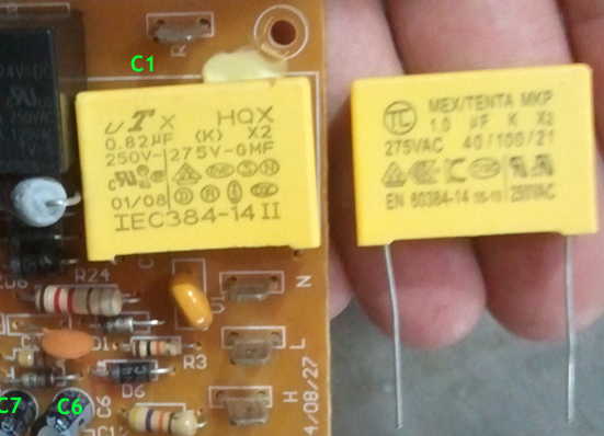
It will be necessary to snap the existing C1/circuit board glue bond before the failed part can be successfully unsoldered.
Trev reports that replacing C1 with the similar 1.0 µF capacitor he’s holding in his hand in the photo successfully solved the problem with his 800ES.
Failure and Repair: Intermittent Operation: No Pump, No Heat.
Kindly contributed by Steve Brown, minor format editing by me. His Breville 800ES is a 240V unit making its home in New Zealand. Here’s his informative and charming tale (spoiler alert: C1 was at fault):My Breville 800 ES went toes up with an intermittent fault. The fault presented as follows: Machine would turn on but the pump would not go through its normal 5 sec burst after turn on and additionally the heater did not turn on. When steam switch was selected nothing would happen, i.e. the pump would not activate. However, occasionally the pump would activate and the machine would work as per usual, so the while the fault was intermittent the fault condition was more-or-less permanent.
Having reviewed your site and after pulling the machine apart I accessed the cct board and carried out some measurements. N.b. I am an ex avionics technician from the RNZAF and professionally qualified but have not been involved with or touched electronics since leaving the air force so I was surprised how quickly my knowledge on SCRs, testing transistors, biasing etc came back… ’twas rather fun!
My measurements determined that the 27 VDC line was being pulled down to 13 VDC. This meant there was not enough potential/voltage for the pump and heater relay to operate once signaled to do so by the Microprocessor. The microprocessor biases Q1 on thereby grounding the earth side of the relay but without the correct voltage being applied across the coil it would not latch and thus mains power could not be applied to the pump and heater.
My knee jerk reaction was that the 24V Zenor was faulty but on reading the posts I considered C1 (0.82 µF 250 VAC) to be a more likely culprit. My Fluke meter has the capability to measure capacitance albeit I’m unsure how accurate this is. In any case, after removing C1 and measuring it, the meter indicated approx. 0.45 µF. At this stage I thought given the readings on your site, the low capacitance reading across the Fluke of the capacitor, and the nature of the fault (i.e. low voltage) it seemed highly likely that C1 was the culprit.
For those Kiwis who may read this be advised that a suitable replacement capacitor (1 µF 250 VAC) can be bought through Jaycar; in my case the Glenfield Branch on the North Shore of Auckland and at a cost of approx. $4 NZ. [Update: site correspondent Keith A. notes that the May 2016 Jaycar price in New Zealand is $5.30 NZ.] I also bought a 24V Zenor at 60¢ just in case the fault was the Zenor.
Long story short, replacing the capacitor fixed the problem. However, the replacement is larger than the original and so it needed to be squeezed on to the board (for want of a better way of saying it) in order for the plastic covers to be refitted on the PCB.
I’m now enjoying my coffees again and it saved me $110 for a new board and $300 – $400 for a new machine… albeit it may be time for a new one.
Seeing a pattern here? On any 800 series espresso machine, though especially any 220-240V units, if you’re having any problems anything close to these, check or replace C1! If you jumped directly to this section without reading through this (very long) page, go to the section above for great details on C1, including selecting and installing a replacement.
Failure and Repair: Relay Buzzes
The relay in a Breville 800 series espresso machine should never buzz. If it does, it is almost certainly being starved for electricity. After site correspondent Louis-Martin A. of Montreal replaced a failed RL1 in his machine, he noticed that RL1 still buzzed, as the old one had. Specifically:
I don’t know if it is normal for that machine, but once the unit is turned on and the heating cycle starts, the heating LED flashes and RL1 does a very weird buzzing.
It goes like this:LED on for 1 second, RL1 buzzes
Thermoblock is heating. […]
LED off for 1 second, RL1 does not buzz.I remember the faulty relay was buzzing too, with the heating LED flashing (and a slight dimming of the power and water level LEDs in rythme with the heating LED flashes, but in a very muffle and inconspicuous. The new relay, however, buzzes like an alarm clock an it is a little anoying, although I could put it on a timer and the breville can, in only one step, wake me up in the morning and getting ready for a dose of coffee!
The only noise RL1 should ever make is a momentary click when it activates and deactivates, which is normally when the machine is turned on, and when it is turned off. The only item in a Breville 800 series which should make any ongoing noise is the pump, when the pump runs. That and water-flow hydraulic sounds are the only normal sounds. The rapid on-off of the relay which creates the buzz leads to all sorts of arcing and contact heating, which is why the original relay failed in his machine.
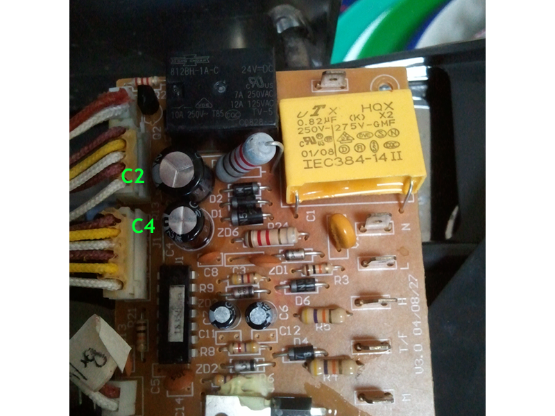
The “smoking gun” is that the buzzing happens when the Heating LED is on. The slight dimming of the Power and water level LEDs is further evidence and seals the case. The relay buzzes because it is starved for power: it just barely has enough for its coil to move the contacts, but not really enough. The power and water LEDs should not perceptibly dim at all… just very slightly when the heating element is actually heating. The relay does not buzz when the heating LED is off because that small difference in power consumption for the LED is enough to shift the relay from Enough to Not Enough power for it to work properly. The V++ power supply is not working properly, and the repairs are the same ones covered in other sections. Fractured solder joints are possible, and should be checked first. Far and away the most common failure is C1 losing some of its capacitance, which “starves” the rest of the machine for power. But it could be C2 or ZD6 itself, or even one or more of the other nearby parts.
On Louis-Martin’s particular machine, this is how the failure happened. He reported that replacing C2 solved the problem—proof that it’s not always C1 which fails. Your Breville 800 may have a different pattern of buzzing. It could be C2, or one of the other V++ power supply parts failing in yours. If RL1 buzzes ever, at all, your machine has a power supply problem.
As of November 2017, we have a second report of C2 being the component causing the buzzing. Site correspondent Soroush from Montreal, Canada has the report:
I removed C1, C2 and ZD6 to do some measurements. C1 was perfect, ZD6 was in great shape but C2 was way off spec. Interestingly enough though my C2 was not the same as you schematic at the beginning of the page. It was 220 MicroF, 50 V 105 degree. Your schematic (Breville) says 100 Micro F, 50V. I re-ordered the correct capacitor and bam all was good. Thought I share this in case it helps someone. As you said, C1 may not always be the bad guy.
This was his parents’ machine. They didn’t notice the buzzing, causing the relay’s contacts to bond together, and the Heating Element Runs When Unit is Off problem. Further note that due to production changes, C2 is supposed to be 220µF in many machines. Replace with the same value currently in yours (unless you want to get into modifications).
Failure and Repair: Intermittent Operation: Intermittent heating. LEDs flicker randomly
Site correspondent G, from a secure undisclosed location in the great nation of Canada, had the following problem:
My machine is experiencing intermittent issues with the heater not working and the LED lighting flickering. Upon opening the machine and inspecting the control board, I noticed a bit of charring on the board and the underside. Upon testing, there appears to be some shorting going on underneath the board.
The shorting happens near C1 and also in the ZD6, R24, D1 and D2 area. When the machine is on, I can cause a short by very slightly pressing on the plastic box (with a very very soft push of one finger).
After an informative back-and-forth email exchange, G and i narrowed in on some suspect solder joints (picture courtesy G, marked up by me):
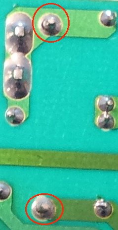
What’s going on is an open, as opposed to short, circuit. Note the solder joints encircled in red. Those happen to be each end of C1 (C1 again!), though in this case capacitor C1 itself has not failed. Overheating, likely due to high resistance of unknown cause (poor factory solder joints are only one of many possibilities) has led to the solder joint between the wire lead of C1 and the metal foil traces of the circuit board failing. The failure is visible as the dark circle (ring) around the middle of the “mountain cone” of each of the two solder joints.
In electronics jargon this is generally called a fractured solder joint, as the solder fails in such a way that the joint electrically and mechanically fractures. I have a whole separate article on this subject. (You may see this same picture over there.)
The fix is straightforward: resolder the fractured joints, and any others which look suspicious. Let’s look at G’s entire board:
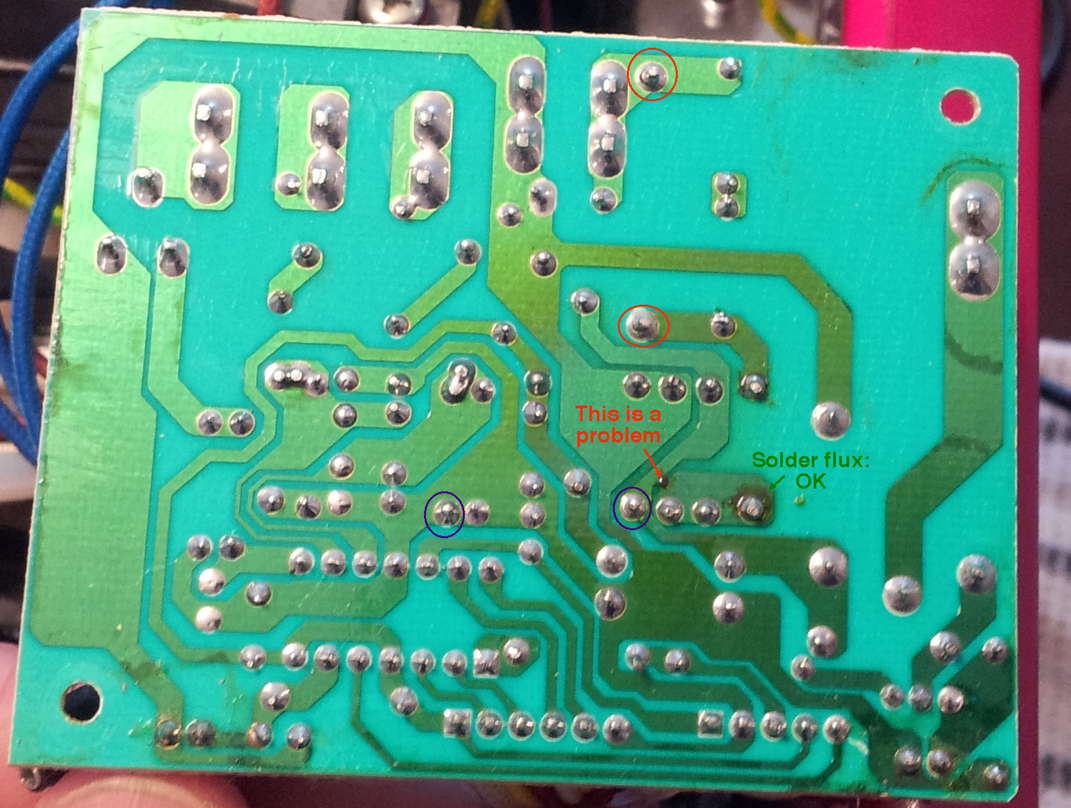
I have circled two other suspect joints in purple, which may or may not be fractured. The spot labeled “This is a problem” is an area where it appears there was an arc between two adjacent foil traces which ought not to be electrically directly connected. This could have happened from molten solder dripping off one of the fractured joints onto this area, melting through the protective coating of the board.
Other visibly unpleasant aspects of this board are not causing problems, will not cause problems, and do not need to be corrected. One of these is marked as “Solder flux: OK”. Yellow or golden or golden brown deposits like this on the foil side of the board are non-conductive flux. These areas can be left alone.
Anyone who’s going to be doing any soldering on these boards owes it to themselves to read the section Preventive Repair: Resolder Questionable Solder Joints below, for important information regarding the protective coating on the foil side of the P.C.B. and RoHS lead-free solder considerations.
Failure and Repair: Any Other Electrically-related Problem: Check Power Supplies
First Step: V++ (24 to 27VDC)
Those of us who know electronics know that power supply problems can cause any number of disparate symptoms. The very first thing to check when your Breville 800-series espresso machine is having electrically-related functional problems (other than those already specifically described above) is whether V++ is at the correct voltage and regulating. Detailed information is in the two sections immediately above: No Power and Intermittent Operation.
ZD6 may have failed in some way other than a total short. C1 may have lost capacity—this has been an especially common failure starting in early 2012 (see the three Failure and Repair sections above, starting here). C2 may have lost capacity. Less likely yet possible: D1 and/or D2 may have failed (shorted, open, somewhere in between). R2 may have changed in value, or gone open circuit.
Whatever the case, until you know that V++ is the correct voltage and regulating (staying within the correct range with changes in incoming line [mains] voltage), you’re wasting your time trying to get the machine working reliably again.
Second Step: V+ (5VDC)
So far, i’ve received no confirmed reports of actual trouble with the +5V power supply in the 800ESXL or related 800-series models. However, this supply is even more critical than V++ in terms of needing to be at the correct voltage and regulating well. Even fairly small deviations from 5V can cause the IC to enter unpredictable logic states and cause who-knows-what sorts of mis-operation.
Again, to date i’ve received no confirmed reports of problems with the +5V supply. If there were problems, historically from other equipment with similar design the most likely part failures would be R24, C4, and ZD1.
Please note that all components of both power supplies are being whacked by power line transients 24/7—they are receiving the full brunt of line [mains] power whenever the espresso machine is plugged in, whether it is on or off. It should not be a surprise that one or more of them will fail over time. Unplugging the 800-series machine or using it on a switched receptacle which is normally switched off may prolong the life of these power supply parts (though personally i don’t bother doing this, myself).
Failure and Repair: Intermittent or Permanent No Heat
In other words: the machine pumps water but it isn’t hot.
Reports started to trickle in regarding this failure as of 2013, with a few more later in the 20-teens. As of March 2024 we now have 4 reports on the outcome (thanks June S., James L., Larry G., and Noel T.!), and even a decade after the earliest reports there is no documented clear repeated failure pattern. Therefore, some troubleshooting is likely to be required (or you can throw a lot of parts at it and hope).
To get started, investigate this crucial question:Is the Tank LED Lit?
From (or near) the productive Quebec workbench of espresso machine wrangler June S. comes the following report:
Hiya. Was working on an 800esxl recently. Refused to heat whatsoever but displayed totally normal behaviour otherwise. Heating LED blinked indefinitely as normal, no matter where knob was positioned.
Machine operated normally minus not having any heat.
Heater element showed regular 15~ ohms resistance.
Zero issues on power/logic board. Swapped in boards from 2 other working machines, issue still persisted.
All thermal switches and thermal fuses OK. Pump OK. Front panel button PCBs OK.
Ended up swapping out the tank illumination LED, and it fixed the issue.
This LED is a strange one-- it is actually two diodes connected in parallel, one LED, and another diode with polarity reverse to the LED. In my case, the LED was dead, but the diode continued to function.Anyway, mystery solved. An annoying one at that!
Yes friends, that white tank illumination LED is a functional circuit component, not merely a user aesthetic feature. But wait, there’s more from wrangler June:
Upon further testing, the parallel diode in the LED is actually a zener diode with a breakdown voltage of 6.75V.
I’m unsure what Breville had in mind here. June S. reports a serial number and photographic information indicative of a Rev. 2 board, which better match my schematic, so we’ll use that for this discussion. Maybe when U1 pin 1 P50 is high—which is any time the machine is turned on—Q2 would start to conduct but as it did the emitter voltage across R20 might rise too high and possibly(?) the C-B junction of Q2 might rise high enough in voltage towards V++ that even with R13, U1 pin 1’s internal circuitry might be damaged? That’s all i’ve got, and it’s such a stretch, my brain is starting to hurt.
When everything is working, the white LED clamps the voltage at Q2’s emitter somewhere in the 3.5 to 4V range. When Q2’s base is activated with something under but close to 5V at the IC side of R13, that’s enough to fully forward bias Q2’s B-E junction and turn it all the way on, at which point Q2’s collector should be somewhere in the, oh i dunno, 3.6 to 4.3V range? (White LED voltage drop plus Q2’s C-E saturation voltage drop.)
When the white LED opens up, with the 6.75V zener, if U1 attempts to turn on Q2, the voltage will rise too high for the 5V from U1 to keep Q2’s B-E junction forward biased. Q2 will not be able to turn on enough (if at all) to energize relay RL1. That zener can’t be low enough in zener voltage to allow circuit operation with white tank LED failure because at any voltage low enough for 5V on the base to turn on Q2, it would steal current from the LED and the LED would not light. I’m still missing why there would be a zener diode in parallel with the white tank LED. I welcome thoughtful analyses, and intend to update this section accordingly once one that makes sense to me gets through my fuzzy skull.
So why wouldn’t Q2 and RL1 operate with just R20, ignoring the white tank illuminator LED and zener?
Specs for RL1, some/many?/all? of which are Song Chuan 833H-1A-F-C 24VDC relays, include a coil resistance of 1,600 Ω and current draw from a 24 VDC supply of 15 mA. Pretend the white LED, zener, and Q2 are all not there, and that RL1 is connected to R20 directly. Well, we’ve got ourselves a voltage divider, and if my illness-fuzzed too-late-at-night calculation is correct, there would be the V++ of 24 or 27V at one end of RL2 and circa 13.9 or 15.6V at the R20 end. That’s about 10-11V trying to actuate a 24V relay. Might work for some 24V relays, and even for others of this brand and model, but might not! If there’s still no Q2 and no white LED, the 6.75V zener clamping the voltage across R20 at that voltage and allowing higher current flow as well yields 17 or 20V across the relay (depending on V++ value), and that ought to be enough to operate most relays with coils rated at 24V. But Q2 does exist, and i cannot see how it could be forward biased and pass current to actuate RL1 when its base cannot be driven by U1 higher than right about 5V.
Even if my circuit analysis is cuckoo coconuts, it makes sense that U1 and Q2 will not be able to power on RL1 unless that white tank LED is present and operational, clamping the emitter of Q2 at or below 4V—and this is what site correspondent June S. reports. Check that tank LED! No light = no hot coffee (or tea or whatever) for youooooooo!
What if the white tank LED is lit up normally? Before you do anything else beyond checking the tank LED, try:Noel’s Workaround/Test
Site correspondent Noel T. of New Jersey’s 800ESXL had the following symptoms:
- Red HEATING LED fails to light during standby warmup (see Normal Sequence of Operations - Breville 800 Espresso Repair step 1)
- Machine operates normally (electromechanically and hydraulically other than the water being cold)
- Turning the knob to the steam wand position makes the red HEATING LED illuminate. After a few minutes, when steam comes out of the wand, the knob may be turned to the brew head position and the machine will produce hot coffee.
Try that last step: put the knob into the steam wand position. If, like Noel T., you eventually get hot water (after the thermal block has a few minutes to heat up), that’s a smoking gun that the low temperature thermostat is open. Looking at the schematic, we see that switch S2 bypasses (shorts across) this thermostat when the water flow knob is in the steam nozzle (turned right) position, to allow the thermal block to rise to the higher temperature needed for steam operation. If the low temperature thermostat is stuck/failed open, with the knob on standby or through-brew-head flow, the power path to the heating element remains an open circuit.
Noel reports that tapping that thermostat (rear-most on our unit, looking at the machine from the usual coffee-making user’s position, but trace the wiring and verify on yours [or tap both]) restored operation, and cleaning the thermostat contacts ensured that normal heating would continue, coffee time after coffee time.
Overheated R24?
Site correspondent Larry G. resolved his heating problems thus:
Startup cycle and pump was working fine, the water would even heat up at first… but after running water through the machine, the temperature would drop and although the thermostats would work and the heating LED would come on, the heater would not kick in.
After opening the casing and looking at the main board, i eventually noticed black hardened soot in between R24 and C1. I decided to change both: a 1.5kOhm 2W and a 1µF 250V capacitor (they didn't have any 1.5, and by reading here I saw that would the job*). I got the parts at Fry’s for a few bucks.
The protective film over the board was a pain, but a few hours in an isopropyl alcohol puddle fixed that (thanks for the tip).
It ended up being R24, it read over 3kOhm. Replaced both parts anyway and it’s working fine now! No more microwaved re-reheated bitter coffee for me.
Bitter coffee! ![]()
* Actually 1 µF is a bit on the low side for a 120V unit, which Larry is almost certainly using given that he conveniently picked up parts at Fry’s Electronics. I have clarified this in the section on replacing C1. Apologies to Larry and anyone else for whom this might have been unclear. Due to circuit tolerances 1 µF might work on some or all 120V units, though once again, if the Breville engineers could have specified 1 µF for everything (all voltages), they would have (saves money).
Other Failures
If Noel T.’s workaround/test fails to work for you, you’ll need to buckle down for some more in-depth, inside the machine troubleshooting. First:- Verify that V++ is stable and within range
This is discussed in the section above. I cannot over-emphasize the importance of this. If you can’t or won’t properly test the V++ power supply, see the section below about throwing parts at the problem.
If V++ is OK, you need to figure out whether the problem lies in the heater circuit itself or the control circuit which operates it. You’ll need a decent multimeter and the skills to use it.
Unfortunately due to major changes Breville seems to have made during the course of production, it is unwieldy to provide a coherent step-by-step which accurately covers both schematic variants. Therefore what follows in the rest of this Failure and Repair section covers ONLY units matching my hand-drawn schematic. It is up to you to adapt these steps to the PDF schematic, if your 800 matches it more closely than my schematic.
- Set your meter to read A.C. voltage. Connect your meter’s common lead to the L terminal: circuit common. Connect the voltage test lead of the meter to the R terminal. Plug in the 800.
- Plugged in and with power Off, you should measure line (mains) voltage.
- With power On, you should measure very close to 0 VAC.
Primary Circuit Testing
You can unplug the machine and do a resistance test, or leave it plugged in and move the meter lead in steps back towards the power source, doing a voltage test to find the failure. I’ll describe the voltage test. The resistance tests works the same way with the unit unplugged, the common lead moved to the N terminal, and the meter set to read resistance (ohms), with the goal being low (near zero) ohms rather than line voltage.
- Measure the voltage at terminal H. If you now have line voltage, the heater may be bad (verify with a resistance reading across the heater terminals [same as from H to R] with power removed). If you still don’t have line voltage, continue.
- Measure the voltage at the common wire between the two thermostats. If you now have line voltage, thermostat 2 (frontmost) may be bad (verify with a resistance reading). If you still don’t have line voltage, continue.
- Measure the voltage on the opposite (not shared with thermostat 2) terminal of thermostat 1 (rearmost). This is directly across the power line and you should be seeing line voltage now. If you’re not, there’s a wiring problem or a problem with your meter or how you’re using it.
Control Circuit Testing
This really needs to be a voltage test to be meaningful. As for the other voltage tests so far, your meter’s common lead should be attached to the L terminal (circuit common).
- Plug in and turn on the 800. With your meter set to A.C. volts, re-check that the R terminal is not close to 0 VAC. If it now is, the problem may be intermittent and you’ll have to wait for it to fail to properly troubleshoot (or throw parts at it).
- Remove the meter’s voltage test lead from the R terminal. Reset the meter to read D.C. voltage (30V maximum). Connect the meter lead to V++ and ensure it is still correct. If it isn’t, the problem should be obvious: go to the section on Check Power Supplies.
- Move the meter DC voltage lead to the collector of Q2. The voltage should be under 5 VDC (approximately). If it is much higher than this, take a quick look to see whether the water tank LED is illuminated. If it is, even very dimly, Q2 has failed. If it is totally dark, continue to the next step.
- Move the meter’s lead to the emitter of Q2. If the voltage is higher than about 5 VDC and the water tank illuminator LED is unlit, the LED has failed. If the voltage is 5 VDC or lower and the LED is unlit, it is likely that Q2 and/or the coil of RL1 have failed (and probably it is Q2), or that Q2 is not being turned on.
- Measure the base of Q2: it should be about 5V with the unit On. If it is much lower or 0, Q2 is not being turned on. Move the meter lead to the other side of the resistor (same as pin 1/P50 of the IC): you should be seeing right about 5 VDC when the machine is On. If you do not, and you are certain that V++ and V+ are both OK (check them again), you are the first person in the world to my knowledge who has a bad IC. You need to replace the circuit board.
- If Q2 is being turned on but the voltage on the emitter of Q2 is 5VDC or lower and the water tank LED is unlit, unplug the machine and measure the resistance across the coil of RL1: it should be roughly 1600Ω, give or take oh say 400Ω or so. If it is very close to 0Ω, D9 is probably shorted (extremely unlikely—no reports of this failure yet). If it is very high, the coil of RL1 is open and the relay needs to be replaced (no reports of this yet).
- If everything above tests OK, that really only leaves the contacts of RL1. Unplug the unit and temporarily jumper terminals R to L (this shorts across the contacts of RL1). Plug the unit in: it should heat up whether it is Off or On. If it does, RL1 needs to be replaced. If it does not, something went wrong in the testing or i made an error or oversight in these troubleshooting steps (contact me with all your test results to this point).
Replacing Q2
Selecting a new Q2
There is nothing particularly special about the 2SC945 transistor. Hundreds of other NPN small-signal transistors can work in this position. All that matters is that the replacement is a general-purpose wire-lead small-signal NPN transistor meeting or exceeding the following specifications:
- BVceo ≥ 50V
- Ic ≥ 100mA (.1A)
- PD ≥ 250mW
- hfe (beta) average ≈ 200
Get whatever is easy to obtain where you live. In North America, a few of many options which should be easy to find include:
- ZTX692B
- BC546B, which should also be easy to find in Europe (its region of origin)
- 2N5232A
Since the supply voltage of the 800-series is not more than 27VDC working, probably BVceo ≥ 35V would be OK, which adds:
- BC547B
- BC237B
- far too many others to list
I did a parameter search at Digi-Key to come up with the part numbers listed above. I’m sure there are many common legacy standard U.S. 2N-series transistor types which will work great, but apparently they’re not sold any more (probably because the U.S. hardly makes anything any more).
Properly specifying/selecting discrete electronic components is outside the scope of this article. If what you see here is insufficient, please consult your usual technical sources for further information. Experts can measure the actual current draw of RL1 and likely get away with a lower Ic and PD value, and as long as the transistor is driven fully into saturation at ambient temperature extremes, it may be possible to get away with a lower hfe value. Such are the considerations of experienced circuit designers (and i know at least some of you reading are exactly that).
For this particular application, it is totally OK to go to your local Rat (Radio) Shack or other convenient local electronic parts store (if such things still exist where you live) and use whatever they suggest. Places like this tend to sell a line of generic replacement transistors (NTE or similar). These tend to be overpriced and not always a close enough match for critical circuits, but for non-critical circuits like this, they should be OK.
Installing a new Q2
During an email exchange with a Breville 800ESXL owner “absolutely new to electronics repairs” having odd problems with a repair, i realized i’d made a major omission in the section above: transistors that look identical may be internally wired differently. This is so basic to those of us in electronics and so obvious to me that i neglected to mention it (nor is this Breville article intended to be a course on basic electronic repairs).
Specifically what i mean is that if one is looking at a transistor in a TO-92 or similar package (like the original 2SC945 in position Q2 in the 800 series machines) with the flat face facing the viewer and the leads pointing downwards, counting the leads left to right 1-2-3:

the lead assignments to the internal elements of the transistor inside the plastic package differ between different parts. 2S transistors, including 2SC945, were originally Japanese designs. For reasons i don’t know, they often (not always) prefer the lead order to be:
Emitter—Collector—Base (ECB)
Americans have always preferred:
Emitter—Base—Collector (EBC)
It is up to You the User to verify the lead arrangement of the replacement transistor you obtain. Consult the data sheet for whichever new part you obtain, then compare it to the known ECB order of the original.
Some transistors may be available with different lead arrangements. The KSC945 from ON Semiconductor available (as of September 2019) through Digi-Key is one example:
KSC945YTA with EBC lead arrangement
KSC945CYTA with ECB lead arrangement (note the C in the part number)
If you want to get a part which you can install exactly as the original with the same lead wire order, you’ll want to order that second part number (with the C).
Failure and Repair: Intermittent or Permanent Weak/Low Heat: Warm but not Hot Water
Possibility #1: Overheated Connections
Some findings are obvious in retrospect once you’re inside the machine. Site correspondent Anil’s Breville 800 had one of those. Here’s his report:
The machine turned on, but the heating light kept flashing red. Switching the knob to espresso resulted in very warm water coming out (as expected, but less hot). Switching the knob to water/steam didn’t do anything—the water/steam lights never lit up.
The problem was the contacts to the heater block were slightly corroded and not making good contact causing them to heat up and worsen the situation. I cleaned them up and attached them again and it seems to be working fine for now.
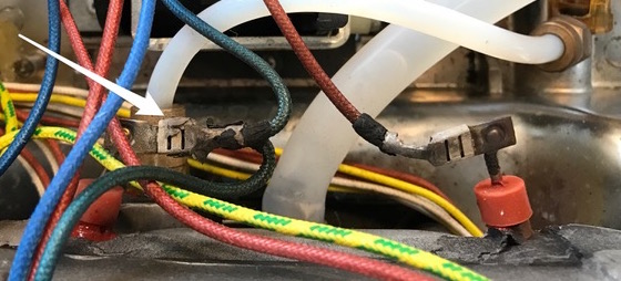
Notice in Anil’s photo how the Quick Connect terminals are discolored from overheating, to the point where the black insulation has cracked and fallen away, especially on the red wire terminal. The metal is no longer a shiny to dull aluminum color, but various shades of brown, chalky gray, and other colors. Any time you have your espresso machine open, please inspect all terminals for visible overheating like this—especially these two terminals attached to the heating element in the thermal block. One nice thing about machines like the Breville 800 is that the metal case is so thick that even when the wiring catches on fire, it won’t likely start a fire in your house (though it might!). It could easily wreck all the wiring and char-broil the circuit board, which could lead to many coffee-free days 😭 (at least from the machine so affected). Clean/tighten/repair loose, overheated connections before you have a fire (and avoid insufficient heat)!
Possibility #2: Thermostats Mis-Operating
Coffee lover Soroush from Montreal, Canada reports:
On a different note, long time ago when we first bought my parents’ machine (online so using the warranty was not an option) the water came out warm and not hot. I tried everything and the only solution that worked was replacing the heat sensors on top of the heating block. Since then all has been good (4-5 years) since this mishap.
Failure and Repair: Intermittent or Permanent Lack of Steam from Wand (liquid water instead)
There are all kinds of Mechanical/Water/Hydraulic failures such as plugged-up steam passageways that prevent enough/any steam from coming out of the wand. You’ll do well to read the section Poor Flow from Steam Wand/General Poor Water Temperature Conditions on another page of this article, as well as the section directly beneath on that page: Poor or No Flow from Steam Wand Even After Wand Cleaning/Decalcification, discussing plugged-up valve and/or thermal block issues and how to resolve them.
As of the end of March 2020, the first report came in of an electrical issue which can cause large drops of hot water rather than steam to emerge from the steam wand/nozzle (and it took me nearly a year to post the information due to personal reasons—sorry!). This section applies if your symptoms are as follows:
- Water flow and temperature through the brew head are totally normal
- Liquid flow through the steam wand seems normal, but it’s water rather than steam even though you’re using the Steam setting (not Hot Water)
Site correspondent Mark F. went through all the decalcification cleaning and valve work described in the sections linked above, with no improvement. He eventually found success by cleaning the contacts on the microswitch to the left (when facing the front of the machine) of the flow selector knob, e.g. this one:
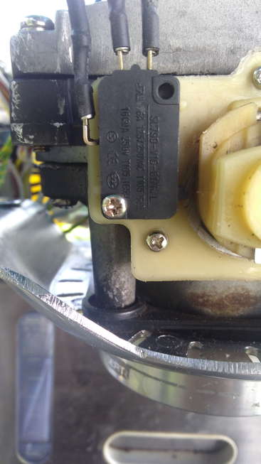
When i made my schematic years before ever seeing the official Breville service manual, i arbitrarily labeled this switch as S2. Breville labels it S1. No matter what the nomenclature, it’s the switch that bypasses (shorts across) the low temperature thermostat when in the Steam Wand flow setting. This bypass is what allows the thermal block to heat to a higher temperature and generate steam.
But what if there is an intermittent connection with this switch? The T/F line will be open, which is correct for the Steam wand flow position. But the thermostat bypass may also be open if there is a loose or intermittent connection, inside the microswitch (very common) or externally to it, on its connection lugs, wires, etc. If you have an ohmmeter (for most people: a DMM set to its ohmmeter/resistance mode), now’s the time to bust it out and do some resistance readings across the N and H connections on the circuit board. Doing this will include all the wiring as well as the microswitch. To test just the switch itself but not the wiring, instead measure across the NO and C contacts at/on the switch, with the knob in the steam wand flow position. You should get a consistently low resistance (under about 5Ω, preferably lower), even when you gently tap on the body of the microswitch with the handle of a screwdriver or similar, with about the force of softly knocking on a door. If the resistance suddenly jumps around when tapping the switch and measuring directly across its contacts, replace or repair the microswitch. I have a whole other article on this site discussing microswitch unreliability and even—gasp!—repairs. Most people will replace microswitches rather than repair them, which is in general a prudent idea, applicable here.
While odds are that it’s the microswitch if you have this particular set of symptoms, it could be something else. Check the rest of the wiring for intermittent connections, which may not be visible at all, via standard resistance testing.
Thanks to Mark F. for sharing this useful information!
Failure and Repair: Cannot select Steam after having selected Hot Water
This one’s really cute: the machine works fine, other than once you’ve selected Hot Water, you can’t go back to steam by pressing the Steam button. The interesting workaround: power the unit off and back on, and there it is on Steam, as its default. It’s like the switch behind the button has failed, or there’s a broken wire or somesuch. The actual failure in our unit proved much more interesting.
I disassembled the unit and measured the resistance across pins 1 & 2 of the 6-pin connector going to the Steam/Hot Water switch/LED assembly. Instead of about 10kΩ, i measured about 390Ω… hmmmm. Question was: was this problem happening on the circuit board, or on the switch assembly? I unplugged the connector and measured these pins on the circuit board: very high resistance. Measured the pins on the cable end: about 390Ω.
Disassembling the small white plastic switch enclosure requires removing the metal front panel, which requires removing the function knob, two rather obvious screws holding the front panel to the chassis center, and loosening/removing the side panels to free the front panel.
Lo and behold, capacitor C10 is squished against the V+ lead of R12:
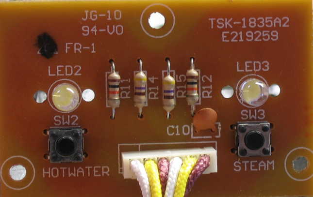
It probably doesn’t look so squished because the picture above is a “re-enactment”, once i’d solved the problem. Initially there was closer and more forceful contact between C10 and the lead of R12. By the mere act of bending C10 upright, resistance testing revealed that the problem was solved. However, there was a new problem once things were assembled again: pushing the Steam button didn’t feel “right”. Turns out that the inside plastic of the button was hitting the top of C10. Bending C10 all the way towards the connector resolved the issue:
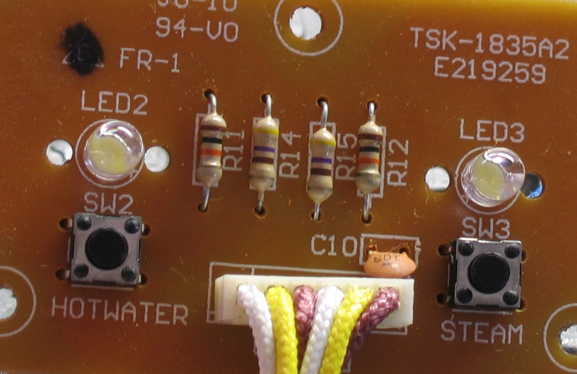
I put it back together and it all works well again. This is another case of theory vs. practice: in theory, C10 has an insulation coating, so that it shouldn’t matter if it is touching another component. In practice the insulation layer is thin/permeable enough that close mechanical contact can allow a very finite resistance between C10 and whatever it touches. Sticking some insulating material between C10 and the lead of R12 ought to work equally well, though for me simply bending C10 all the way to the opposite side was easier. (The insulation on the connector is very thick, so there should be no problems at all with C10 touching the outer plastic of this connector.)
Failure and Repair: Soldered pins pulled out of printed circuit board
Site correspondent and latte lover James L. provides this handy tip:Standard 1.6mm board pins are a good replacement for the connector for the LED and switch, should someone else pull theirs off the board. They make sense for the switch, but the circuit won’t work correctly without the LED as the voltage at the emitter or Q2 will be too high, so I’d recommend just unscrewing the LED per your guide. The LED also serves to hold the emitter voltage low.
I soldered some pins in for the switch connector. Since they are fairly tall, I bent them 90 degrees and can plug in the connector from the side.
Preventive[2] Repairs
Preventive Repair: Remove Unintentionally Conductive Glue
Unintentionally conductive glue is a whole story unto itself. I really thought that everyone had wised up to this stuff a decade or so ago and ceased using it… apparently not. As discussed at length in my article linked from that last sentence, it is normal and necessary for manufacturers to use an adhesive to hold big parts in place during wave soldering. This adhesive usually serves no purpose afterwards… it just sits there benignly. Unfortunately some adhesive formulations have proven to become chemically unstable: they “break down” under heat and become partially conductive. If they are in contact with circuit wiring, they create phantom electronic components that can really mess up a circuit—sometimes.
Our 800ESXL had/has some of this glue, and it started to become conductive, partially connecting the non-powerline end of C1 to the anodes of D1 and D6 (circuit common, e.g. line hot), and the cathode of D2 (V++). Now, in this particular case, the conductive glue probably did not and might not ever have made a difference, since this is a high-current low-impedance area of circuitry: not that sensitive. If conductive glue were connecting more sensitive areas of circuitry, such as any pins of the microprocessor IC or the switches connected to it, things could be more exciting. The Breville engineers seem to have done a good job keeping this adhesive away from sensitive areas. Yet, given what i have seen, as soon as i saw it (and well before i had drawn out the schematic to see that it was in a low-sensitivity part of the circuit), i removed it, and i recommend anyone already working on their circuit boards do the same. Probably not worth a special trip into a working unit, yet if there is any other reason to be in there, take it off and make it a non-issue. Only the brown, crusty parts need to be removed (mechanically, followed by your favorite solvent)… the light tan/gold soft, springy parts may remain, which is good because they often are still happily acting as a strong adhesive and do not willingly come off.
Preventive Repair: Replace Overheated Parts
It was visually obvious by the peeling paint and discoloration that resistor R4 (47kΩ 1/2W) was running too hot in our particular 800ESXL. Though it had not yet failed, i replaced it with a 1 watt resistor, to hopefully avoid a future repair.
Some people also like to replace D1 and D2, given that they run hot, as evidenced by discoloration around the printed circuit board near them. I’ve not personally done this on the machine here and those parts continue to work well, but if there’s any doubt and you’d rather not go back inside, they’re inexpensive. If you’re going to go to the trouble, i suggest standing them up off the circuit board a bit to allow better air flow.
Preventive Repair: Resolder Questionable Solder Joints
What initially appeared to have been the source of the “Pump Motor Runs When Unit is Off” problem seemed to have been the totally lousy solder joints on every joint on this particular circuit board.
Probing with my multimeter, i found virtually none of the joints showed continuity across that same joint. Now, it may be that the factory applied a protective insulating coating (which i now know was a conformal coating), yet still each joint was a uniform gray, indicative of poor wave soldering during manufacture.
The (tedious) solution?:- Clean the conformal coating off the back of the board. I did this in an inelegant manner (an overly strong solvent, not evenly applied). Contributor Doug McNutt provides us a more elegant solution:
“The coating on the back side of the board interferes with soldering. An overnight soak in a plate with enough dry isopropyl alcohol to cover the solder side but not the component side and it was all gone.” - Remove the existing solder (maybe… it did not play nice with my solder. I have old lead-based solder and this device is new enough to maybe have RoHS lead-free solder).
- Resolder every joint with good, fresh solder.
- Carefully reconnect the wiring and plug in the 800ESXL, still disassembled. Test all functions for correct normal operation before reassembling.
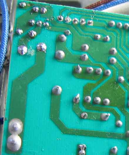
The picture above shows a lot of original grey joints, some partially unsoldered joints in the top center, and some freshly resoldered shiny joints in the top left.
Whether or not to go to this effort is up to you. I have no clear proof that there was a problem, yet it sure did not look good, so i resoldered mine.
Other Approaches
Not A Troubleshooter? In a hurry?: Throw Parts At The Problem
I highly recommend that anyone who has evolved to the level of decent soldering skills go the slight extra distance to do proper troubleshooting and replace only the parts that are necessary. However i have (finally) realized that i shouldn’t force my preferences and world view upon others: throwing parts at a problem is wasteful of materials, but can be a lot faster in terms of time and requires only understanding how to procure the correct parts and solder them in place, not how to troubleshoot. It may also be the only option when one lacks test equipment and/or the ability to use it safely and properly.
I do Not promise that the suggestions which follow will cure your particular problem—they may well not! That’s the point of troubleshooting! However, given that there are known, common failures in the Breville 800 series, the odds are pretty good that “shotgunning” certain failure-prone parts may solve your issue.
If you want to go this way—and remember i am not recommending it—try this:
- Check for fractured solder joints and repair any you find, or that are questionable
This alone might fix the problem, so test your machine afterwards. Didn’t fix it? Continue…
- Replace ZD6 and C2
- Replace C1, especially if you live outside of North America
- Replace any parts which appear overheated. See Preventive Repair: Replace Overheated Parts above
- Only if you’re having intermittent heating problems: replace Q2, and if the tank LED is out, replace it as well
- Do the SCR mods
Looking at it another way: you can always skip the troubleshooting and ASSume that the parts listed in a given section related to your problem elsewhere on this page also need replacing in your particular machine. You may well waste time and money obtaining and changing parts which were perfectly fine, yet if you’re successful, you may have saved troubleshooting time and even test equipment purchases/loans.
Easy, Expensive Repair: Replace The Circuit Board
Well, actually, i suppose if you’re one of those people who gets paid well for whom “time is money”, board-level replacement may be easy and inexpensive. Also, if you’ve determined that the microprocessor itself is indeed at fault (i have yet to see this myself), board replacement is likely to be the only option, as the IC is a custom chip. In any case, if for whatever reason, board-level replacement is what you’re into, Ian L. shares the following:
I found the e-replacement website that sells the entire circuit board with the side boards/switches/buttons. I also called Breville directly and requested the part, but they have a policy not to sell internal components to individuals. They did give me the number to a Texas authorized repair shop: Fort Worth Shaver and Appliance. I called them via 817-335-9970 and talked to a technician for about 15 minutes. He was very helpful with telling me about his experience fixing the machines. He sold me the same part that e-replacement offers for $80 something with shipping included. Maybe I'll get another year out of this machine, maybe several, but it's been a fun project and I feel good about it. =)
In terms of the ease/difficulty of doing the board swap, Ian followed up a couple of weeks later:
I got the new main board/side board/buttons in today. Put them all in and it worked like it never broke. Easy as cake. Wish it wouldn't have cost me $80 and change, but now you have another fix solution for your website.
In October 2012, site correspondent Dan shared another North American source for the PCB:
Forum Home Appliance in Vancouver, BC stocks the part for [C]$17.50 plus about $15.00 for shipping.
When doing link checks on 7 January 2015, i found that the price has increased to C$49.68, and it is a limited stock item. It was listed as no longer available as of 20 March 2018, and as of 19 November 2025 the page is gone. (You’re welcome to look for an archived version of this page, or view the page source of this page revision for the commented-out link, if you want to try and see what used to exist.)
“Just to update, I called Texas based Fort Worth Shaver and they don’t have the 800esxl pcb’s nor do they service them anymore. The canadian website also doesn’t sell the pcb’s either.”
I’m leaving the older information in place as a reference for prices, when the boards were available. If anyone finds another source for whole boards, let me know and i’ll look into adding that information in this section. This is an older discontinued model, so it’s entirely possible that there are no more new boards.Have any Breville 800ESXL repair tips? Send ’em in! I’ll endeavor to add the seemingly good ones to these pages, at my usual glacial pace. (Please let me know if you want to be credited or remain anonymous. Thanks!)
[1] And another couple of days redoing it as a digital diagram and all the other things related to setting up this web page. You’re welcome… if you haven’t already (and many of you have… Thanks!), hope you’ll return the favor to all of us repair types in the future.
[2] Long not sure of the difference, if any, i did a couple of minutes of research, and found an interesting article claiming that “preventive” is the preferred form. Praise be to the Internet Archive and their Wayback Machine!
- Breville 800 Repair Home
- Normal Sequence of Operations
- Disassembly
- Electrical/Electronic Issues
- Mechanical/Water/Hydraulic Issues
- Modifications
 World O’ Appliances/Household/Plumbing/Irrigation/HVAC/Hardware