Blower Cycling Oddity
Running Again for No Good Reason
Failure Background
The furnace has been running well since the prior repairs. I’ve rotated the inducer grommets a few times when i’m visiting and hear the inducer motor running more noisily than it should, and that’s been about it. Several times over the past couple of years, i have noticed that my mother’s Day & Night-badged 376B (specifically, a 376BAW036075) would run what seemed like a normal cycle, then after a minute or so the blower would start up and run again, without an intervening call for heat, or any flame/inducer cycling. Was this furnace’s blower getting all theatrical, and wanting an encore?!
Early in 2018, i’d heard it happen often enough that i could no longer ignore it. I waited for the end of the heating season and pulled the control board during the summer. Actually i took the whole circuit chassis with bogus kludged-in repair power transformer (definitely not original) plus all the paper documentation on the furnace, plus the blower panel with its special wiring diagram (more detailed than in the paper manual) home with me, to thoroughly understand how the HH84AA021 control board (sometimes known as the 1010-83-919B, and on the actual board HH84AA21, with no leading zero) operated with various sensor and signal inputs. This page is mostly the story of my findings.
Meet The HH84AA021
Many days into this project, i happened to do some WWW lookups, and found that the HH84AA021 is a replacement control board. Can’t say that i’m terribly surprised, since the original power transformer burned out and was replaced by a quickie hack job (by an HVAC professional, on the clock no doubt). This was the board (and power transformer) i remember seeing the first time i worked on this furnace, or at least the first time i paid attention to the control board.
Had the HVAC professional followed the replacement board’s installation instructions and left those selfsame instructions with the homeowner, i likely would not have needed to spend hours reverse-engineering the circuit, and doing the research which culminated in this web page. They didn’t; i did. As of January 2019, this board and similar drop-in replacements remain available in the replacement parts market (at least in the U.S.). For that reason, i won’t bother posting a photo of the board, which you can find on many other sites. For those who want to read the informative installation instructions, as of the original web posting date of this page, Arnold’s Service Co Inc. kindly makes them available in PDF format. What you won’t find on other sites (that i’ve seen) is the schematic of the board:

That’s a lot to take in. Please take some time to study whichever aspects are of interest to you, then we’ll continue.
Careful viewers will notice that a few components are not fully specified. For example: Z1, Z2, Z4. C8 is not specified at all. That is because this is a working board, and to read those numbers i would have had to unsolder these components, then resolder them. Not in the mood to do that on a working board.
Other information wouldn’t readily fit on the schematic, and is easier to type here. Mostly, that’s information on the relays:
- K1: Potter & Brumfield T9AS1D12-22 22VDC Form A (S.P.S.T.) N.O. 30A 120 & 240VAC
- K2: Potter & Brumfield T9AS5D12-22 22VDC Form C (S.P.D.T.) N.O. 20A 240VAC, N.C. 10 A 240VAC
- K3: Takamisawa LZ-B24H-C 24VDC S.P.S.T. N.O. 1/8HP 120/240VAC, 4A 240VAC resistive, 5A 30VDC/120VAC resistive
Circuit Analysis
Obviously the heart of the circuit is IC U1, which takes the various input signals and uses them to operate the relays in a sensible manner for both normal and abnormal operating conditions. The Microchip PIC16C54-RCI/P is an 8 bit 4 MHz microcontroller, with 512 12-bit words of memory. Each of the 12 I/O pins on this device may be software controlled to be inputs, outputs, or switch between the two. Here’s a simplified diagram of the IC’s inputs and outputs, in this particular circuit:

In this circuit, it appears (from the externally connected hardware components) that pins are permanently dedicated to being inputs, or outputs. The actively-used inputs uniformly have a series 15V ½W zener diode, resistive voltage divider dividing the input voltage by half (10kΩ series then 10kΩ to ground), and 10 nF filter capacitors. The one exception is the input for the G-Blower Option, which is either 2 resistors dividing the IC’s supply voltage down ⅒th. on pin 18 (around 0.47VDC of pure D.C. measured on my actual board), or one resistor pulling pin 18 up to the zener-regulated 5.1VDC VDD (with Z1 probably being a 1N5231) sourced off B+.
From a pure D.C. perspective, the inputs lacking the 1kΩ 3W resistors to chassis behave as expected: 0 volts on the IC pin when there is no input, and 1.66VDC at the IC pin when there is a 24VAC input to the appropriate terminal. On the other hand, those inputs with the 1kΩ 3W resistors to chassis (IC pins 1 & 8) change little in terms of D.C. voltage.
An oscilloscope is needed to see the full reality. Looking at the IC pins on the ’scope, the ones lacking the 1kΩ 3W resistors to chassis go from a flat line 0V to a 6V peak half square wave. The inputs with 1kΩ 3W resistors to chassis have that square wave present all the time. The key is its timing shifts from opposite the other inputs when off, to matching the other inputs when on. I am guessing that the IC may only be testing the inputs during particular points on the powerline waveform cycle.
Pins 9 through 11 are interesting. All of them relate to potentiometer PT1: the Blower Off Delay control. Pin 9 is clearly an input, connected to the wiper of the pot. There is no reason i know of that the fixed ends of PT1 could not have been connected to VDD and VSS, a.k.a. circuit common a.k.a. P.C.B. ground in this circuit. Measuring with a voltmeter on all of pins 9 through 11, each pin has a significantly low voltage. The oscilloscope shows another story: waveforms on each pin, from a small triangular wedge on pin 11 of about 1.5V at its peak to a 5.1V low duty cycle half square wave on pin 10. Pin 9’s waveform is between the two of these, depending where PT1 is set. The circuit designers are clearly far more clever than i am, for which i applaud them.
Pins 12 and 13 are clearly outputs. Pin 12 drives Q2 which drives 120VAC output blower/electronic air cleaner relay K1 and 24VAC output humidifier relay K3. Pin 13 drives Q1, which drives blower speed relay K2. These are clean pure D.C. 5.1VDC On/0VDC Off signals on the IC pins.
Circuit Operation
Fail-Safe Operation
The first interesting thing to note—critical to the issue i’m working on—is that if any part of fusible link and Hi Limit series path opens or fuse F1 blows, there will be no 24VAC to terminals R & GH, thus no signal on IC pin 7. U1 is programmed to continuously run the blower at low speed when F1 blows or the link/limit loop opens or jumper JW1 is cut. The installation instructions warn that cutting JW1 is only an option for heating-only applications, never when cooling is part of the system.
For the remainder of this operation discussion, let’s assume that F1 and the link/limit loop and JW1 are all intact, so that Pin 7 sees its 6V peak half square wave and blower operation is on normal cycles rather than continuous-on safety fallback.
Normal Operation
Heating Cycle
R is the 24VAC source terminal for the thermostat for heating, with GH being the same for cooling (if needed. Electrically they’re the same point when JW1 is intact, which per the instructions it must be for cooling applications). The heat thermostat will call for heat by completing the circuit to terminal W. W does little on this board, other than send the call for heat 24VAC to the inducer motor control circuit and gas valve control. Those other circuits with start the inducer motor immediately (it tracks W’s call for heat signal), and the pilot ignition sequence, eventually leading to ignition of the main burners. None of the pilot lighting nor main burner control happen on this board. Soon as the main gas valve opens and the main burners light, P4 pin 3 delivers 24VAC to IC pin 6 (converted to lower-voltage D.C. at the actual IC pin), initiating the up count timer. Once the up count timer hits 60 seconds (50 seconds per the documentation, but a full minute in actual testing of the board i have), IC pin 12 activates relays K1 for blower power (120VAC) and K3 for optional humidifier power (24VAC) and IC pin 13 activates relay K2 for low-speed blower operation.
When the call for heat ends and terminal W drops back to 0, the inducer motor and main burner shut down. Disappearance of 24VAC heading (eventually once processed) into IC pin 6 starts the blower off delay timer. The specific blower run time after cessation of main burner operation is adjustable between approximately 80 and 240 seconds (a.k.a. 1 min. 20 seconds and 4 minutes) via PT1. Once this timer times out, IC pins 12 & 13 drop low, releasing all 3 relays back to their open positions (Normally Closed for K2).
Cooling Cycle
The cooling thermostat sources 24VAC from either R or GH, on a call to cool delivering it to terminal Y (and the wholly separate wiring and circuitry to the compressor unit). This signal on Y goes to IC pin 1. With the factory configuration, signals at the Y terminal have no effect on furnace blower operation. I’m guessing that normally there would also be 24VAC at the G terminal, covered in the next section.
Cooling Cycle Part 2 and Fan Only
For either cooling blower operation or a Fan Only call from most thermostats, terminal G is supplied with 24VAC. The IC immediately outputs an On signal on pin 12 for relays K1 & K3. Relay K2 is not energized, thus the blower runs at high speed. As soon as the 24VAC is removed from the G terminal (whether using the thermostat’s Fan function or as part of its cooling cycle function), the relays de-energize immediately, shutting off the blower with no delay.
G-Blower Option
This option is disabled when the board ships from the factory. Cutting (or, if you’re couth rather than uncouth, unsoldering one end of) R18 enables the G-Blower option. When enabled, a G signal, such as for Fan Only, runs the blower at low speed rather than the default high speed. No G signal is needed for cooling, with the Y signal now the one activating the blower at high speed for cooling cycles. With G-Blower Option, the termination of the Y signal starts a 90 second blower off delay timer.
Out-Of-Furnace Testing
Setup
- Remove the entire control board chassis with power supply from the furnace. Take it to your test bench.
- Wire up 4 S.P.S.T. switches (whatever you like) as shown in the diagram below. Start with all switches open.
- Wire up at least 3 120VAC lamps (i recommend incandescent or neon, but use whatever you like) to the Hi and Lo blower terminals and EAC1 (and the Com or EAC2 terminal), as shown in the diagram.
- Wire up 1 24VAC lamp between terminals H and C, as shown in the diagram.
- Optional: if you’re curious when K2 is On versus Off, put a 24VDC lamp across D7. If it’s polarity-sensitive such as an LED with series resistor, mind the polarity when you hook it up.

Yes you may omit some of the switches and lamps if your system lacks humidifier and/or cooling hardware, and you don’t care about those functions.
Here’s what my test setup looked like:
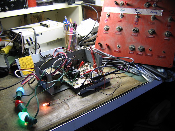
I happened to have the old (1960s) switch panel, which saved me having to mount the switches and made labeling easier. The Main Burner heat switch is the one unreadable due to the fluorescent test bench lighting. A failed holiday light string (had some bad sockets) was easy to cut up for color-coded indicator lights. The Humidifier lamp was a 24ESB 24V telephone slide base lamp i happened to have.
Testing
These steps are interdependent. You may have to consult previous steps if you skip any.Fail-Safe
- Supply 120VAC to L1 and L2 on the board. With all switches open, all 3 relays should energize to run the blower at low speed. The Lo, EAC, H(umidifier) and optional K2 lights should all be lit.
- One at a time turn on the Burner switch (then turn it back off), then the Cooling switch, then the Fan switch. Nothing should change, in terms of the lights. All switches should again be Off when this step is concluded.
Standby and Heat Cycle
- Turn on the Limit switch and leave it on. All lights should extinguish.
- With some form of stopwatch or equivalent, start the stopwatch at the moment you turn on the Burner switch. Leave this switch on until further notice. Verify that all of the Lo, EAC, H, and optional K2 lights light up around 50 seconds after you turned on the Burner switch. With my board it’s 60 seconds, not 50. Not sure whether this was a production change or original documentation error.
- Reset the stopwatch. Start it back up afresh as you turn off the Burner switch. Verify that all of the Lo, EAC, H, and optional K2 lights remain lit for between approximately 80 and 240 seconds, and that the exact time is roughly proportional to the setting of PT1. When this time is reached, all lights should go off.
Cooling Cycle
Turn on the Cooling switch, to the Y terminal. If the G-Blower Option is disabled (factory setting: R18 intact), nothing should happen. If the G-Blower Option is enabled (R18 missing, cut, or unsoldered), the Hi, EAC, and H lights should light up. In this latter case, start a stopwatch as you turn Cooling back off. The same lights should remain lit for around 90 seconds.
Fan Only and Normal Cooling
Turn on the Fan switch. In the factory configuration of the G-Blower Option being disabled, the Hi, EAC, and H lights should light up, and should go off immediately once the Fan switch is turned off. If the G-Blower Option is enabled, the Lo, EAC, and H lights should follow that same pattern.
Turn on the Heat switch then the Cooling switch. Nothing should change. End of test.
Troubleshooting: Blower runs another low-speed cycle with no additional call for heat
Now that we (especially i) have an understanding of normal operation of this circuit, a very likely cause jumps out: chances are excellent that the circuit is intermittently going into safety fallback. The one thing that i can see that can cause this to be a repeating pattern is the self-resetting Hi Limit switch opening, then later re-closing.
Why might this happen? Well how about because on this particular board as i first found it, PT1 is all the way down—the opposite of “Inc” for Increase. In other words, the blower off delay is at the minimum of about 80 seconds.
Starting with this theory, i needed to test it. I reassembled everything back into the furnace, running it with the control cover (the big one) off and with my digital multimeter set to A.C. voltage across the Hi Limit switch. Sure enough, once the furnace had run a nice few minutes’ normal cycle and the blower (prematurely) shut off, residual heat in the combustion chamber ramped back up until the Hi Limit switch opened, driving the board into fail-safe mode, starting the blower back up on low speed.
The obvious solution was to Increase the setting of PT1. I experimented with turning the pot halfway up. The air was still quite warm when the blower shut off (i didn’t time it), so i experimented with arbitrarily setting it to 3/4s rotation towards INCrease. This setting (which i also neglected to time) allows just a touch of air coolness before the blower shuts off. Now rather than running a too-short final heat delivery and cooldown then needing the Hi Limit to trip and run an additional cooling cycle, the singular, normal longer-running final heat delivery and cooldown cycle gets the furnace cooled down enough that the Hi Limit no longer needs to trip. Additionally, there ought to be less waste heat, since the residual hot air is blown out of the duct work (which is a very long run on this installation) rather than dissipating from it as would happen when the blower shuts off prematurely.
Failure and Repair Summary
I have the utmost respect for true professionals in every field. It is well established that i am Not an HVAC professional. We all know that not every person in every line of endeavor is good at what they do. Indeed some are terrible. This particular failure was the result of someone who i’m sure is or was an HVAC professional, but not good at what he* did (*had it been she, i would’ve heard about that from my parents at the time. They would have found it novel, back in the early 1990s).
- This failure would never have happened if the HVAC professional had set PT1 properly.
- I would not have spent time reverse-engineering the circuit and putting up this page (at least in this level of detail) if the HVAC professional had followed the replacement board installation instructions and left those printed instructions with the furnace or my parents for inclusion with the rest of the furnace documentation. With only 4 installation steps and the word MUST (in all capitals like that) on the step requiring leaving the instructions with the furnace/furnace owner, there is no excuse (other than not being able to read written English, which in the area where the furnace is installed, is a distinct possibility).
 World O’ Appliances/Household/Plumbing/Irrigation/HVAC/Hardware