Originally written and posted 2 June 2001
Content last modified
Monday, 18 August 2025
External links last verified Friday, 8 June 2018
There has been a great deal written about X10 Wall Switch modules, including many modifications for meeting several objectives. It used to be possible to visit the Home Automation Knowledge Base Wall Switch Modification (Dead Link, remaining here for archive research purposes) page and ferret around there for all sorts of useful information compiled by fellow X10ers. Since the demise of Ido Bartana’s site, one now has to search around and hope.
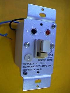
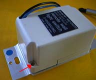
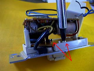
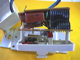
The purpose of this page is to provide a pictorial description of WS module disassembly, to hopefully help make the process easier and less frustrating.
Last i checked, the Home Automation Knowledge Base only had an illustration for the new-style Wall Switches. Hence these images. It used to be possible to visit the Home Automation Knowledge Base Wall Switch Modification page for details and background information on the local dimming modification not presented below, but no longer.
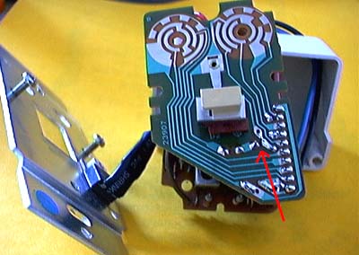
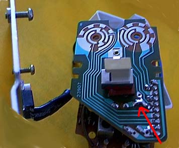
Briefly, by merely adding one solder bridge to the P.C.B., a standard X10 Wall Switch Module gains the local dimming function. Dimming is achieved by pressing and holding the on/off button. The light will cycle between full-on to full-dim, then back to full-on. Let go at the desired brightness level. Brief presses still execute standard local On and Off, as before.
Be sure that the pushbutton switch contacts are clean and operation reliable before reassembling and installing.
Basically the reverse of disassembly, with a few helpful tricks.
World O’ X10 ![]()
![]() The Sonically Pure Pages
The Sonically Pure Pages
This Siber-Sonically Pure Page is ![]() and
and ![]() Transitional compliant.
Transitional compliant.