Road Sensing Suspension Wheel Position Sensor Repair
Fancy cars have extra problems, relative to simpler models. GM’s Continuously Variable Road Sensing Suspension (CVRSS, or just RSS) used on some higher-end vehicles such as my parents’ 1998 Cadillac DeVille, can be very nice… when the system works.
Troubleshooting DTC RSS C1760 LF Position Sensor Input Fault
Diagnostic Trouble Code (DTC) RSS C1760 LF Position Sensor Input Fault started appearing a couple years ago (early 2020s), with LF being the left front wheel position sensor. Surprisingly often the fix may be as simple as reconnecting the mechanical link between the sensor and the that wheel’s control arm. No such luck in my case: electrical problem.
More or less followed the factory service manual’s diagnostic procedure, adjusting for the vehicle not being operable at that point. Unfortunately for me, nothing else simple like chafed wiring. Went off the reservation (e.g. outside the FSM diagnostic steps): decided to measure the D.C. resistance at the CVRSS module C2 connector to each sensor.
Measuring D.C. resistance with the meter’s resistance/positive (red) lead on the first contact listed in the table below and the common/negative (black) lead on the second contact listed below of CVRSS module connector C2, i immediately found a discrepancy between the left front and the other 3 wheel sensors:
| Sensor | 8V Supply (Reference Feed) to Sensor Return | Strut Position Signal to Sensor Return |
|---|---|---|
| Left Front | A8-B8: 33.6 kΩ | A9-B8: 242 kΩ |
| Right Front | A10-B10: 4.3 kΩ | A11-B10: 8.5 kΩ |
| Left Rear | A3-B3: 4.3 kΩ | A4-B3: 8.9 kΩ |
| Right Rear | A5-B5: 4.3 kΩ | A6-B5: 8 kΩ |
Obviously the left front values are far off from the other 3 sensors, which reasonably match. Got the same too-high resistance values at the left front sensor’s connector, confirming that it wasn’t a wiring harness problem.
Repairing the Left Front Position Sensor
Yes, i typed repair.
Why Not Replace?
That’s what GM had in mind, but that was at the end of last millennium. You go ahead and try and find a part number 22154001 Wheel Position Sensor. In late September/early October 2025 when i did so, i found:
- Very few New Old Stock or New Substitute (couldn’t tell which), for US$400s of dollars and up.
- Used salvage pulls on ebay for US$90+, which might be no better than what i had.
Sensor 22154001 might not have been designed to be repaired, but why not at least try?
Repair
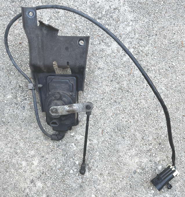
- Remove sensor assembly from vehicle
- Remove sensor itself from the bracket
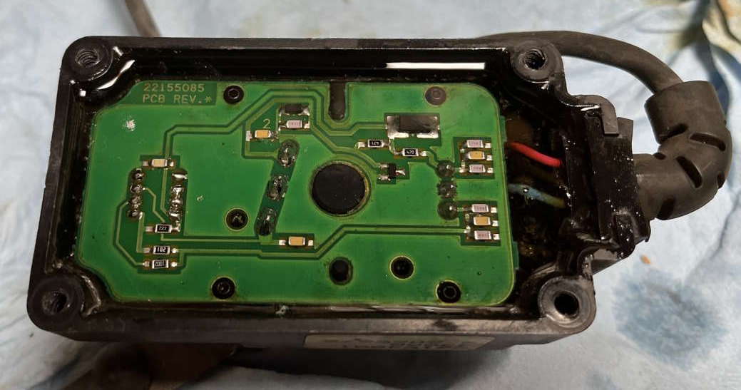
To my delight, found a metal cover plate covering the back of the sensor, which lifted right off once the sensor was unscrewed from the bracket. Better: the electronic potting material GM used is highly translucent, so it’s possible to see the printed circuit board (PCB). Even better: the potting material is removable for service access! Maybe GM did intend for these sensors to be repairable!
- Visually inspect the PCB. Initially through the potting compound, i saw no issues.
- Check the D.C. resistance of each sensor wire from the sensor connector to the PCB. All 3 tested low resistance (≤2Ω) on mine: Good, Pass.
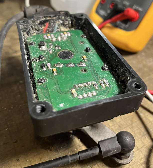
This is where i needed to dig out the potting compound for deeper troubleshooting. Started by cutting the potting compound away from each side with a utility knife. Then using various screwdrivers, picks, old toothbrushes, etc., it was pretty easy to get the potting compound out down to the level of the foil side of the PCB:
Found nothing obvious, so decided to reverse-engineer a schematic for the sensor circuit:

Circuit Description
I could go on and on with thoughts about this circuit design (and did, before editing that long ramble out). Tl;dr is: looks like an excellent analog circuit design to me.
The resistance element attached to the sensor arm is fed by an extremely precise, tightly regulated voltage, thanks to regulation in the CVRSS module to create the 8VDC sensor supply, then precisely regulated further down to 5VDC ±0.5% by the precision shunt regulator. The resistance element’s output is amplified and buffered by one half of what appears to be an op amp IC. There was no need for me to get to the component/opposite side of the PCB, hence i have no idea whether that IC is marked, and if so, what part number it is. The way it’s wired into the circuit matches a number of common 8 pin mini DIP op amp ICs going back several decades, and it makes sense to have an op amp in this position wired into this sort of circuit, so chances are good that’s what it actually is. The strong, filtered sensor output is robust enough to traverse the vehicle’s wiring harnesses to the CVRSS module and supply that module with clean data… when the sensor is working properly.
Let’s get back to that now.Failure Diagnosis and Repair Continued
- Test all fixed resistors: measure for correct value. All passed.
- Test variable resistance element resistance
This is where things got weird: results seemed inconsistent. Despite having drawn a conventional potentiometer on the schematic, i am not at all certain that that’s how this sensor element is built. It seems like a passive variable resistor, but maybe not quite. Because i did not disassemble it to get inside—which might have destroyed this part i needed working again—we can’t know what’s in it. I do know that the wiper goes to infinite resistance relative to at least one of the fixed terminals, i think towards the high limit position.
I’m not certain about this part’s resistance for several reasons:
- My initial assumption regarding the terminal layout was incorrect, and my documented readings are a mish-mash of incorrect and correct terminal layout measurements.
- In-circuit resistances were/are affected by either or both of the rest of the circuit in parallel and/or internal circuitry in the resistive element package itself. I did not take the time to fully unsolder the contacts to isolate the 3 element terminals from the rest of the circuit.
- Even measuring the same terminals under the same conditions, readings varied. (← This is your spoiler alert.)
Knowing that this failed sensor had a significantly higher resistance than the other three when measured at its terminals, and now having a schematic of the circuit, my next troubleshooting step was:
- Evaluate the equivalent D.C. resistance circuit between each connector pin, then measure to locate any source of discrepancies.
I decided to start with measuring between connector pins B and C. At first glance this might not seem possible: B connects to the output of the op amp. But there is a straightforward D.C. resistance path from terminal B through the 1 kΩ output resistor, “up” through the 2.2 kΩ resistor to V+, “down” the 470 Ω resistor through what should be the fixed resistance part of the sensor’s variable resistance element to circuit common (ground) and terminal C.
Getting values of 3.3 kΩ to 3.9 kΩ for the sensor’s fixed section and adding 470 Ω + 2.2 kΩ + 1 kΩ, we get approximately 7 to 7.6 kΩ theoretical resistance between terminals B and C. The actual measured value for the other 3 sensors on this car ran between 8 and 9 kΩ (Strut Position Signal to Sensor Return column of the table near the start of this article), yet this one measured 242 kΩ.
Working around this resistive loop, i finally found what i probably should have noticed earlier:
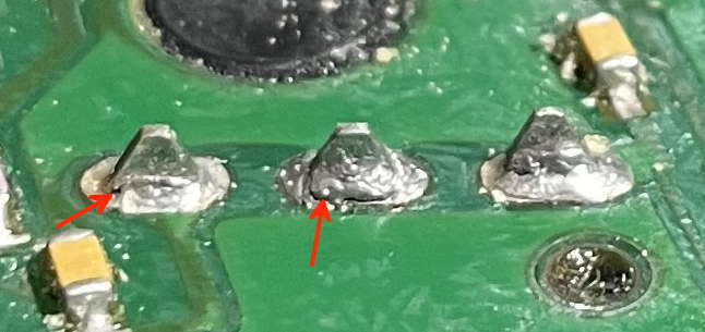
Fractured solder joints on the resistive element’s terminals—at least 2 if not all 3 of them! Red arrows point to the most obvious dark “black line” areas of fracture visible in this photo. I have a whole other article about fractured solder joints, where (if you go there) you’ll see this picture again.
The fact that the joints fractured strikes me as weird, because mechanically the board and sensor seem unable to move relative to each other. Maybe with really hard blows/bumps they do? Maybe improper factory soldering? I don’t know. I do know what the next repair steps are:
- Resolder fractured solder joints, as well as any other questionable joints:
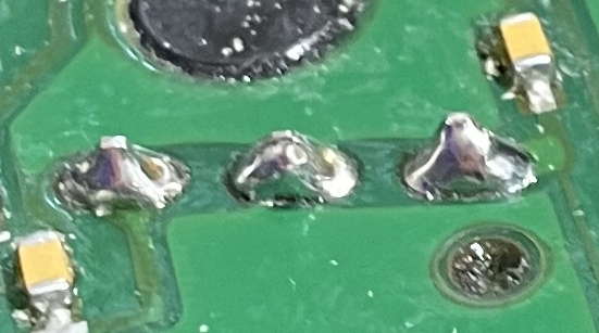
- Retest D.C. resistance at sensor connector terminals. Pass!
Yes, those are not the greatest re-done solder joints. I consider them adequate, and if i’m wrong, i may be doing this job over in the future. Once resoldered, the measured resistances matched the other 3 sensors: 4.11 kΩ from A to C and an even 8.0 kΩ from B to C.
It seemed to make sense to add an additional test step:
- Bench test sensor operation powered with +8VDC power supply:
- basic operation
- internal voltage regulation
- smooth, consistent output changes with sensor arm movement
- output spans expected voltage range
Attached a regulated 8 VDC power supply to pins A & C, and a DMM in D.C. voltage mode black (common) lead to pin C. Measured the shunt regulator voltage at 5.002V: 0.04% high—well within the 0.5% tolerance specification. Connected the DMM’s red (voltage) lead to pin B for the remainder of the tests. Output voltage varied smoothly between a minimum of 0.32V and a maximum of 4.8V, which as far as i’m concerned matches the FSM claim of 0 to 5V (RSS Position Sensors Description on p. 3-211 of volume 2 of 3 of the Second Edition of the 1998 Cadillac DeVille, DeVille d’Elegance, Concourse, Eldorado service manual GMP/98-EKS-2F).
Electrically the sensor seemed to work fine. Time to repot and reassemble!
- Repot sensor with “digoutable” (removable for repair) polyurethane potting compound, hopefully compatible with the factory original potting compound
Honestly, this was the step that took the greatest amount of time with this repair. I’d removed potting before, but had never potted or repotted anything. Days of research finally led me to narrow choices down and select a transparent polyurethane-based compound purchased from Amazon. Seemed to work well for me:
My schedule allowed plenty of time—days—for the potting compound to fully cure. It was fully cured and could have been used within the time frame on the product label, but i felt better having allowed it the additional time. Continuing with the repair:
- Reassemble sensor body on mounting frame
- Before installing sensor, electrically connect its connector to the body wiring harness connector. Re-check resistance measurements at CVRSS module connector C2. Passed.
- Reinstall sensor in vehicle per FSM
- Reconnect CVRSS module connector C2 and otherwise reassemble parts of vehicle as needed
- Clear RSS DTCs (if necessary)
Summary of Diagnosis and Repair Steps
It’s pretty tough to follow the steps with all the intervening commentary, so here i repeat them as one contiguous list, sans commentary:
- Remove sensor assembly from vehicle
- Remove sensor itself from the bracket
- Visually inspect the PCB. Initially through the potting compound, i saw no issues.
- Check the D.C. resistance of each sensor wire from the sensor connector to the PCB. All 3 tested low resistance (≤2Ω) on mine: Good, Pass.
- Test all fixed resistors: measure for correct value. All passed.
- Test variable resistance element resistance: Fail, or at least Inconsistent
- Evaluate the equivalent D.C. resistance circuit between each connector pin, then measure to locate any source of discrepancies.
- Resolder fractured solder joints, as well as any other questionable joints
- Retest D.C. resistance at sensor connector terminals. Pass!
- Bench test sensor operation powered with +8VDC power supply:
- basic operation
- internal voltage regulation
- smooth, consistent output changes with sensor arm movement
- output spans expected voltage range
- Repot sensor with “digoutable” (removable for repair) polyurethane potting compound, hopefully compatible with the factory original potting compound
- Reassemble sensor body on mounting frame
- Before installing sensor, electrically connect its connector to the body wiring harness connector. Re-check resistance measurements at CVRSS module connector C2. Passed.
- Reinstall sensor in vehicle per FSM
- Reconnect CVRSS module connector C2 and otherwise reassemble parts of vehicle as needed
- Clear RSS DTCs (if necessary)
Conclusions
Late 1990s GM RSS Position Sensors can in at least some cases be repaired! So far, the repair on this particular sensor is holding. Should that change during my remaining lifetime and awareness of this vehicle’s DTC status, i intend to update this article accordingly.
While there is insufficient data (as far as i know) to know how common or rare fractured solder joint failures are in these sensors, given the punishment these sensors receive in normal driving, storage in weather extremes, etc., it seems reasonable to particularly focus on fractured solder joints when starting an attempted repair, and especially sensible to focus on the three joints between the PCB and the resistive sensor element itself.
Happy Well-Suspended Motoring!