Figure 1
This section provides information about unpacking and inspection, jumper selection for speed, restart inhibit, fast forward control, audio switcher control, tape timer control, meter switch selection, CARTSCAN switch selection, mounting and wiring.
The CTR100 is shipped in a specially constructed packing carton to protect the equipment during transit. Carefully unpack the unit using care to avoid damage to the recorder finish. Check the contents of the packing carton for any damage that may have occurred during shipment. Notify the carrier of any damage. All packing material should be retained for inspection by the carrier. It is advisable to retain the carton for future use.
The CTR100 is normally supplied wired for 7.5 i.p.s. operation. The unit may also be operated at 3.75 i.p.s. or 15 i.p.s. by removing the 7.5 i.p.s. jumper and installing the 3.75 i.p.s. or 15 i.p.s. jumper on the TONE SENSOR board.
To change motor speed remove the mu-metal cover from over the circuit boards and carefully unplug the TONE SENSOR board. Remove the four screws holding the electrostatic shield to the TONE SENSOR board and put the shield aside. Unsolder the jumper from position W3 and solder it to W1 for 3.75 i.p.s. or to W2 for 15 i.p.s. Replace the electrostatic shield. Carefully plug in the board and replace the mu-metal circuit board cover.
Jumpers may be installed to prevent the machine from starting if the STOP lamp is flashing (cartridge played), preventing double plays of the same cartridge.
The START function may be inhibited if the lamp is flashing slow, fast or at either rate. The CTR100 is normally supplied with no jumpers installed (no restart disable).
To add restart disable jumpers, remove the mu-metal cover from over the circuit boards and unplug the LOGIC board. Solder in jumper W1 [W3 if not used] to inhibit the START mode if the lamp is flashing slow or W2 [W4 if not used] to inhibit the START mode if the lamp is flashing fast. Both jumpers may be installed to inhibit the START mode anytime the STOP lamp is flashing.
NOTE: Removing and reinserting the cartridge will reset the lamp flash circuit and the cartridge may be replayed. It is suggested that disable jumpers not be used if your station records more than one selection on a cartridge or adds additional programming to pre-recorded carts. Read Sections 2.2.3 - 2.2.5 before replacing the LOGIC board.
All machines are standard with SECONDARY cue tone, and FAST FORWARD. An excellent use of the SECONDARY cue tone is to record the tone at the end of the message to initiate FAST FORWARD at the END of the tone. To implement this feature, install jumper W12 on the LOGIC BOARD.
NOTE: If it is desired to initiate FAST FORWARD at the BEGINNING of the tone, install jumper W11 instead of W12.
The audio is automatically muted in the FAST FORWARD mode.If an automatic FAST FORWARD function (Section 2.2.3) is not desired, it is still possible to mute the audio at the end of the message. Record a SECONDARY cue tone at the end of the message and install jumper W15 in the LOGIC board to mute the audio at the BEGINNING of the cue tone, or W16 to mute the audio at the END of the cue tone.
If a SECONDARY cue tone is recorded at the end of the message it is possible to use the SECONDARY cue tone to freeze the tape timer. The timer would then display the time between the START command and the SECONDARY cue tone, indicating length of message. To freeze the tape timer at the BEGINNING of the SECONDARY cue tone, install jumper W13 in the LOGIC board, or install jumper W14 to freeze the timer at the END of the SECONDARY cue tone. Carefully reinsert the LOGIC board and replace the mu-metal cover.
The VU meters may be used to monitor audio record bias, cue record bias and cue signals as test functions in addition to conventional program audio on record and monitoring of playback modes.
The test functions are discussed in Section 5.
Meter select switches S2 and S3 are located on the TONE GENERATOR board and may be accessed by removing the mu-metal circuit board cover. There are several choices of audio metering, selected by four position switch S2:
These choices are available either for discrete stereo input material in which switch S3 has to be on INPUT/OUTPUT position, or for discrete STEREO, MATRIX or MONO recording in which case S3 is switched to TAPE/OUTPUT position.
In the latter case, input audio level is metered after the discrete STEREO, MATRIX and MONO switching network.
In MATRIX RECORD mode, L+R is displayed on the left meter and L-R is displayed on the right meter. In MONO RECORD mode, L+R is displayed (and only recorded) on the left track. Metering is normal in the standard stereo record mode.
Examples of typical switch setup:NOTE: S1 should be in its center (normal) position, and S4 should be in its center (off) position.
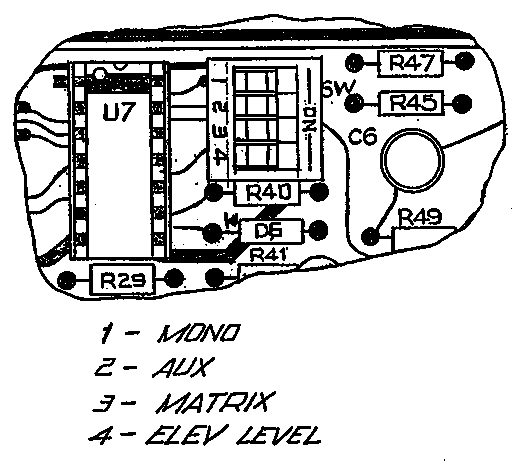
Carefully replace the mu-metal cover.The CARTSCAN System senses an optically encoded label placed along the right side of the cartridge and automatically activates MONO, MATRIX, ELEVATED LEVEL and AUXILIARY functions. The normal mode is to switch a function on when the reflective area is present. If it is desired to have a function normally on and turn off when the reflective area is present, it is necessary to set the proper inversion switch on the PLAY AMPLIFIER (fig. 1). Remove the mu-metal cover and unplug the PLAY AMPLIFIER. Carefully replace the PLAY AMPLIFIER after setting the proper inversion switch.
NOTE: More than one inversion switch can be used at one time, however, the MONO and MATRIX switches should not be used together.
The Dynamax CTR100 Series is designed for table top mounting. An optional rack adapter and filler panels are available for mounting in a standard EIA 19" rack. The CTR100 series of machines are 5 1/4" high (without feet). The “A” size reproducers are 5.875" wide, allowing three machines to be installed side by side in a 19" rack opening. The “B” size recorders are 8.75" wide allowing two machines to be installed side by side in a 19" rack opening.
When mounting the equipment, allow sufficient space at the top, bottom and rear of the unit to permit a flow of cooling air. For this reason, desk mounted units should not have the feet removed. Ventilation holes in the top and bottom covers should not be obstructed.
Main AC power is connected to the recorder/reproducer through a power supply AC cable equipped with standard connectors. To attach the cable, simply insert the female plug at one end of the cable to the male AC power receptacle on the rear panel, being certain to press the connector well into the socket on the machine. The other end of the cable may be plugged into a standard AC outlet.
The CTR100 is equipped with a universal power transformer capable of operating at 120 or 240 VAC. See Figure for power conversion wiring information. [No such figure in this section of the first edition of the CTR100 manual.] The DC Servo motor and universal power supply allow operation at 50 to 60 Hertz without modification.

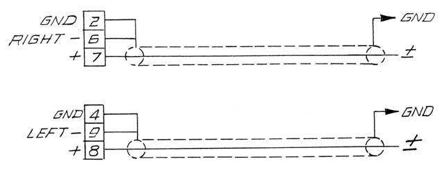
NOTE: This is a bridging input. Some audio sources (especially transformer coupled) require proper termination for flat frequency response and proper output level.
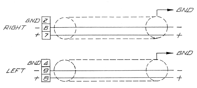
NOTE: This is a bridging input. Some audio sources (especially transformer coupled) require proper termination for flat frequency response and proper output level.
NOTE: If the load is a bridging input (not 600 ohms) add a 600 ohm resistor from the “+” to the “-” terminal.
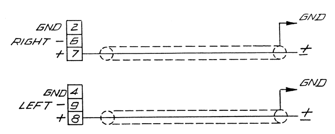
NOTE: If the load is a bridging input (not 600 ohms) add a 600 ohm resistor from the “+” to the “-” terminal.
Proper grounding is important to prevent RF pickup and ground loops. A grounding strap should be connected from the rear panel ground terminal to the studio or station ground. Most hum and noise problems can be corrected by improving or altering the grounding. If a hum loop or RF pickup occurs, one or more of the following suggestions will usually cure the problem:
NOTE: The machine is fully functional upon removal of the remote control plug. No jumpers are required to operate without the remote control.
All lamp outputs are open collector current sinking output, maximum 15 VDC open circuit voltage, 80 mA.
[Original hard to read 2-column dot-matrix printout text converted into an HTML table by Sonic Purity, January 2019]
| CTR100 Pin Number | Pin Function | FUNCTION |
|---|---|---|
| 1 | Output | Auxiliary start pulse — momentary (100 msec.) pulse to ground upon start of tape motion—open collector. May be used to start an external clock or timer. Maximum 15 VDC open circuit voltage at 200 mA. |
| 2 | Output | MATRIX lamp |
| 3 | Output | ELEVATED LEVEL lamp |
| 4 | Output | AUDIO lamp |
| 5 | Output | SERVO ERROR lamp |
| 6 | Not used | |
| 7 | Output | SECONDARY lamp |
| 8 | Input | RECORD switch — momentary contact to ground will place the machine into record. Second contact initiates 1 KHZ DEFEAT. Activation while in RECORD or START mode records PRIMARY cue tones. |
| 9 | Input | TERTIARY record switch — contact to ground will record a tertiary cue tone. |
| 10 | Output | FAST FORWARD lamp |
| 11 | Input | FAST FORWARD switch — momentary contact to ground will place the machine in the FAST FORWARD mode. Holding contact to ground will unmute audio during FAST FORWARD operation. |
| 12 | Output | STOP lamp. NOTE: This lamp illuminates and flashes in synchronization with the front panel lamp. |
| 13 | Input | STOP switch — momentary contact to ground will stop the machine. |
| 14 | +15 VDC | |
| 15 | GND | |
| 16 | Not used | |
| 17 | Interlock | STOP lamp interlock — connecting this pin with the same pin of other machines will synchronize the flashing of all STOP lamps. |
| 18 | Interlock | Audio switcher interlock — connecting this pin with the same pin of other machines will interlock the audio switchers. Only the last machine started will pass audio; all others will be muted. |
| 19 | Output | MONO lamp |
| 20 | Output | AUX lamp |
| 21 | Output | 1 Hz — 1 Hz, 15V square wave clock output — for external timer. Frequency varies with motor speed, i.e. 3 Hz in 3x fast forward. Max. load 10k ohms. |
| 22 | Output | VARY SPEED lamp |
| 23 | Output | 1 KHZ DEFEAT lamp |
| 24 | Output | TERTIARY lamp |
| 25 | Input | SECONDARY record switch — contact to ground will record a secondary cue tone. |
| 26 | Output | RECORD lamp |
| 27 | Output | SPLICE lamp |
| 28 | Input | SPLICE switch — momentary contact to ground will place the machine into the splice find mode. |
| 29 | Input | START switch — momentary contact to ground will start the machine. |
| 30 | Output | START lamp |
| 31 | Not used | |
| 32 | Not used | |
| 33 | Not used | |
| 34 | Output | Ready lamp. This output goes low when a cartridge is inserted and is in the stop/ready mode. |
| 35 | Output | Clock reset — normally high, goes momentarily low when front panel timer resets. |
| 36 | Input | VARY SPEED control — contact to ground will place the machine into the VARY SPEED mode. |
| 37 | Output | TERTIARY cue relay — normally open contact (see pin 47). |
| 38 | Input | Cue bias — contact to ground will turn on the cue record bias. |
| 39 | Not used | |
| 40 | Output | Aux tone — logic output from the auxiliary tone detector. Normally low, goes high (+15 VDC) when tone is present. NOTE: Aux tone is a special function not normally used. |
| 41 | Output | CUE track out — audio output from the cue track booster amplifier. Maximum load 4.7 k ohms. |
| 42 | Output | 9600 Hz output — servo motor crystal reference 15V peak square wave. Max load 10 k ohms. |
| 43 | Output | Motor tachometer output — servo motor tach output 300 Hz at 3.75 i.p.s.; 600 Hz at 7.5 i.p.s.; 1200 Hz at 15 i.p.s. Max load 47k ohms. |
| 44 | Output | Secondary cue relay — normally open contact (see pin 46). |
| 45 | Output | Clock control — logic output low to freeze digital timer, high +15 VDC when timer is counting. |
| 46 | Output | Secondary cue relay — normally open contact (see pin 44). |
| 47 | Output | Tertiary cue relay — normally open contact (see pin 37). |
| 48 | Input | VARY SPEED input — oscillator input for Vary Speed control; 9600 Hz will produce normal jumper selected speed. |
| 49 | Input | Cue audio input — logging input to the cue record amplifier. |
| 50 | Not used |