Section 3 — Operation
(original pages 44-62)
This section describes functions and location of the recorder/reproducer controls and indicators, and provides general pre-operating procedures and operating instructions for various modes of operation.
3.1 Pre-operating Procedures
- Turn off the CTR100 rear panel power switch. Clean and demagnetize the components in the tape path.
- Make all required connections and complete all installation procedures before applying power to the recorder/reproducer.
- Turn the rear panel power switch to the “on” position. The SERVO ERROR lamp will illuminate and then extinguish indicating the motor has accelerated and reached normal speed. The front panel digital timer on record machines will read 00:00.
3.2 Front and Rear Panels – Controls and Indicators
Power Switch
Located on the rear panel of the unit. Used to turn AC power on and off.STOP Switch
Used to stop all tape motion and to cancel the RECORD set mode.Ready Lamp
Contained in the STOP Switch, the ready lamp is on when the cartridge is properly loaded or when the cleaning switch is on, indicating the machine is ready to start. The ready lamp will flash at a slow rate after the cartridge has cued and will flash at a fast rate if the cartridge has been manually stopped.START Switch
Used to place the transport into normal motion. The START mode may be entered from the FAST FORWARD, SPLICE or STOP mode. When starting from the STOP mode, the ready lamp must first be illuminated. When entering the START mode from FAST FORWARD, the audio will remain muted until normal speed is achieved. The machine will remain in the START mode until another mode is selected or a tone is reached.Start Lamp
Contained in the START switch, this lamp indicates normal tape motion.FAST FORWARD Switch
Places the machine in the FAST FORWARD mode. May be entered From the STOP (if ready), SPLICE, or RECORD mode. The RECORD or SPLICE mode will automatically be cancelled. Audio is normally muted in FAST FORWARD; holding the FAST FORWARD button in will cause the audio to unmute. The machine will remain in the FAST FORWARD mode until another mode is selected or a stop tone is reached.Fast Forward Lamp
Contained in the FAST FORWARD switch, this lamp indicates that the transport is in the FAST FORWARD mode. When entering the START mode, the lamp will remain lit until normal speed is achieved and the audio is unmuted.TERTIARY Record Switch (Recorders Only)
Used to record a tertiary cue tone. This switch functions in the START as well as in the RECORD mode.Tertiary Cue Lamp
Contained in the tertiary record switch (Recorders Only) or behind the blackout panel (Reproducers Only). Indicates the detection of a tertiary cue on the tape.SECONDARY Record Switch (Recorders Only)
Used to record a Secondary cue tone. This switch functions in the START as well as in the RECORD mode.Secondary Cue Lamp
Contained in the secondary record switch (Recorders Only) or behind the blackout panel (Reproducers Only). Indicates the detection of a secondary cue on the tape.RECORD Switch (Recorders Only)
This switch is used to place the machine into the RECORD/ready mode only when the transport is in the STOP/ready mode. Pushing the RECORD button twice when the transport is in the STOP/ready mode will defeat the automatic 1 kHz primary cue tone record function. Additional 1 kHz stop tones may be recorded by pushing the RECORD switch when the transport is in the START or RECORD mode. Tone duration is determined internally and is not dependent on holding the switch.Record Lamp (Recorders Only)
Contained in the RECORD switch, this lamp indicates that the machine is ready to record (RECORD and STOP/ready lamp) or is recording (RECORD and START lamp).SPLICE Switch (Recorders Only)
Places the transport into the splice find mode. The transport will operate at the fast forward speed and will run until a splice is found (machine stops and ready lamp flashes slow). Another mode can be selected while in splice find mode if for some reason the operator decided to stop splice finding. The splice finder uses a thickness detector and is safe to use with recorded tapes. No erasure takes place. Entering SPLICE mode will cancel RECORD mode. Audio is muted during the SPLICE mode.Splice Lamp (Recorders Only)
Contained in the SPLICE switch, this lamp indicates that the machine is in the SPLICE [find] mode.Digital Timer (Recorders Only)
Displays 00:00 (minutes and seconds). The display is reset when a cartridge is inserted, or started from the STOP mode. Exception: the display will not reset when entering the RECORD and START mode if the 1 KHZ DEFEAT has been programmed. The timer displays accurate time in all modes including SPLICE and FAST FORWARD, and during VARY SPEED operation. The display accelerates and decelerates with the tape.Left Input Level Control (Recorders Only)
Used to adjust the left channel record input level.Right Input Level Control (Recorders Only)
Used to adjust the right channel record input level.AUDIO Indicator
Indicates that the audio switcher is on (preamp unmuted). Illuminates when going from any mode to START. Extinguishes when leaving the START mode. In addition, the audio switcher may be turned off when starting another machine if the audio switcher interlock remote control terminals of all machines are wired together. [LINK]See remote control pin 18 (Section 2.6.8).VARY SPEED Indicator
Indicates that the motor is under external speed control. [LINK]See remote control pins 36 and 48 (Section 2.6.8).SERVO ERROR Indicator
Indicates that the motor is not running at the proper speed. It is normal for this indicator to light on initial powerup or when the motor is accelerating or decelerating.1 KHZ DEFEAT Indicator (Recorders Only)
Indicates that the RECORD switch was pushed twice while the machine was in the STOP/ready mode, thus defeating automatic recording of the 1 kHz primary cue tone.MONO Indicator
Indicates that the CARTSCAN System will record and/or play a mono format cartridge. In record, the left input is summed with the right input and recorded on the left track. During playback, the left track preamplifier will supply signal to both the left and right output amplifiers, providing a mono output.MATRIX Indicator
Indicates that the CARTSCAN System will record and/or play a matrix format cartridge. In record, the left input is summed with the right input (L+R) and recorded on the left track. A difference signal (L-R) is recorded on the right track. During playback, the left and right channels are recombined to produce the original left and right signals, yielding mono-compatible stereo, free of phase cancellation errors.ELEV LEVELS Indicator
Indicates that the CARTSCAN System will record and/or play an elevated level cartridge. The ELEVATED LEVEL mode brings into operation a secondary set of output level, record level, record bias and record equalization controls, allowing separate optimization for two different tape formulas and/or levels.AUX Indicator
Indicates that the CARTSCAN System has switched a logic signal at [LINK]remote control pin 20 (Section 2.6.8).Cleaning Switch
Located in the front of the right cartridge edge guide. Screwdriver accessible from the cartridge slot. When switched on (up position) the start switch is enabled allowing the pressure roller to be cleaned from the front of the machine, and additional diagnostics to take place.
3.3 Operation
3.3.1 CARTSCAN System
The CARTSCAN System automatically, without operator intervention, allows the intermixing of cartridges recorded in Mono, Stereo or Matrix Stereo at Elevated or Standard level and, in addition, provides a signal to activate auxiliary equipment such as a Dolby encoder/decoder.
The CARTSCAN System uses special optically encoded labels, available from Fidelipac, to switch the recorder and, subsequently, the reproducer, to the proper format. The label is affixed to the right side of the cartridge prior to recording. There are four basic CARTSCAN modes:
MONO
Allows the intermixing of mono and stereo cartridges. Pre-recorded mono cartridges with this label affixed may be reproduced in stereo CTR100 machines. A mono output will appear at both the left and the right outputs. Affixing this label to blank cartridges will allow mono recordings to be made in stereo CTR100 recorders. The left and right inputs will be summed and recorded on the left channel (upper) audio track.MATRIX
Affixing this label to pre-recorded stereo matrix cartridges will allow them to be reproduced in a stereo CTR100. The CTR100 contains the proper decode circuitry and no external equipment is necessary. Affixing this label to blank cartridges will result in a stereo matrix (L+R recorded on the left track and L-R recorded on the right track) recording when used with stereo CTR100 recorders.ELEV LEVELS
Allows the intermixing of tapes recorded at standard level with those recorded at elevated level. Factory calibrated CTR100 recorders record 4 dB higher in the elevated mode with reference to the standard mode. Input and output levels are automatically normalized. The primary audible difference is a 4 dB improvement in signal-to-noise when in elevated level mode. ELEVATED LEVEL should be used with high coercivity tapes (such as Series 500 HOLN) available from Fidelipac.AUX
Allows the intermixing of cartridges which require external processing, such as noise reduction, with those that do not. An auxiliary logic output is available at the remote control to activate external equipment.
Labels are available for the following CARTSCAN combinations:
- MONO
- AUX
- ELEV LEVEL
- MATRIX
- MONO, AUX
- MONO, ELEV LEVEL
- AUX, ELEV LEVEL
- AUX, MATRIX
- ELEV LEVEL, MATRIX
- MONO, AUX, ELEV LEVEL
- AUX, ELEV LEVEL, MATRIX
- Blank (no optical encoding)
NOTE:
- If neither Mono nor Matrix labels are used the Stereo machine will record and reproduce stereo audio.
- While the CARTSCAN label is normally used to initiate one of the above modes, a mode may be permanently left on without a label by using the appropriate CARTSCAN inverting switch ([LINK]See Section 2.4). The presence of a CARTSCAN label would turn the preselected mode OFF. If the inversion mode is selected, extra care must be taken when selecting the proper label.
EXAMPLE: If a library of Mono cartridges is available, and if it is desirable to play them using the Mono CARTSCAN mode without a label, the Mono inversion switch must be engaged. If new cartridges are to be recorded in Stereo, ELEVATED LEVEL mode, label F must be affixed to the cartridge. The MONO section of the label would cancel the preselected MONO mode and the ELEVATED LEVEL section of the label would turn on the ELEVATED LEVEL mode.
Peel the seif-adhesive label off of its backing. Align and affix to the cartridge as shown below. The cartridge surface should be clean and grease free (fig. 6).
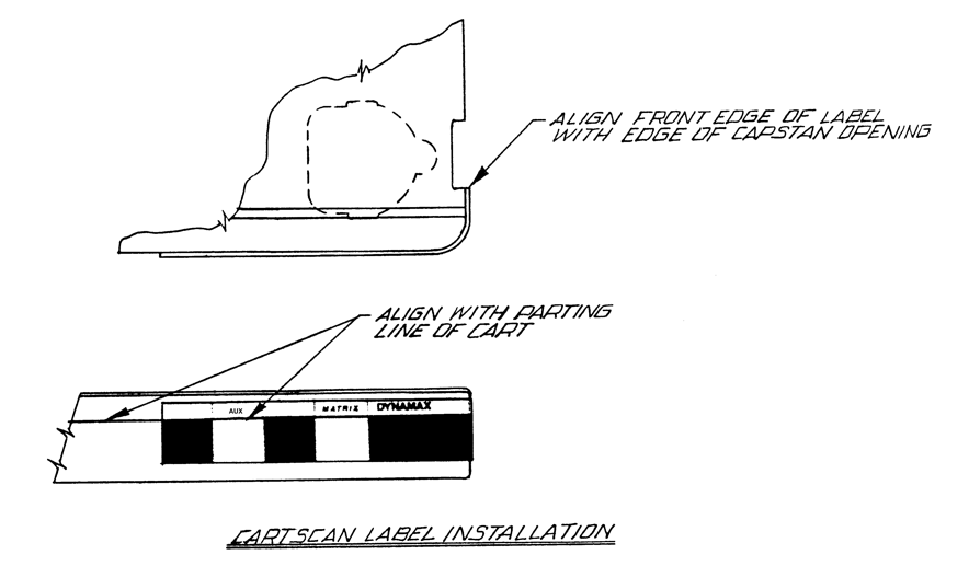
Figure 6
NOTE: The CARTSCAN System sensitivity has been factory adjusted to just trigger when the optically coded area of the CARTSCAN label is present. Some cartridges have a highly reflective surface and may falsely trigger the CARTSCAN System when no label is attached. If this occurs, the side of the cartridge should be blackened with a permanent marker, or a blank CARTSCAN label (available from Fidelipac) should be affixed.
3.3.2 Recording
- Bulk erase the cartridge to be recorded.
- If desired, install a CARTSCAN label.
- Insert the cartridge into the recorder. The ready lamp will illuminate and the CARTSCAN Status Display will indicate the mode of recording, if a CARTSCAN label has been used.
- Locate the splice if desired.
- Push the RECORD button. The record lamp will illuminate.
- Preset record levels should correspond to an average reading of -1 to 0 on the VU meter(s) before the cartridge is started.
NOTE: VU meter select switches must not be in the PLAY ONLY mode. [LINK]See Section 2.3.
- When the level is set, recue the material to be recorded. Start the recorder, wait 1/4 second and start the material to be recorded. This delay allows for the pressure roller to engage the tape and initial flutter components to stabilize. The digital timer will reset to zero when the recorder is started. A 1 kHz stop tone will automatically be recorded on the cue track at the beginning of the recording. The AUDIO indicator will illuminate.
- If desired, a Secondary cue tone can be recorded on the cue track at the end of the recorded material ([LINK]See Section 3.3.6 A). If previously selected, the secondary cue can cancel RECORD, mute AUDIO, freeze the timer and pIace the machine in FAST FORWARD. The machine will stay in FAST FORWARD until the stop tone is reached. See Sections [3 LINKS]2.2.3, 2.2.4 and 2.2.5.
- The record process may be terminated by pushing the STOP button, removing the cartridge (when the stop lamp is illuminated), pushing the FAST FORWARD or SPLICE switch, performing step H above (if applicable) or waiting for the cartridge to cue up automatically at the 1 kHz stop tone. The AUDIO indicator will extinguish.
NOTE: Pressing the RECORD button twice before pushing the START button will defeat the automatic 1 kHz record function and prevent timer reset. The 1 KHZ DEFEAT indicator will illuminate.
3.3.3 Playback
- Insert a pre-recorded cartridge into the transport, The ready lamp will illuminate and the CARTSCAN indicator will display the format of the recording if a CARTSCAN label has been used.
- Place the cartridge in motion by momentarily pressing the START button. The AUDIO indicator will illuminate.
- The cartridge will continue to run until a stop tone is sensed or the cartridge is stopped manually. In addition, the cartridge may be placed in the FAST FORWARD mode manually or automatically (if a secondary tone is sensed and a FAST FORWARD initiate jumper is installed) [LINK]See Section 2.2.3. The AUDIO indicator will extinguish.
- The playback mode may be initiated from the FAST FORWARD mode. Audio will remain muted until normal speed is reached.
3.3.4 FAST FORWARD
- The FAST FORWARD mode may be initiated manually from the STOP mode (if the ready lamp is on) or from the PLAY or SPLICE mode.
- The audio is muted in the FAST FORWARD mode but unmuting is possible by holding the FAST FORWARD button depressed.
- FAST FORWARD may be initiated automatically if a secondary tone is sensed and a FAST FORWARD initiate jumper is installed. [LINK]See Section 2.2.3.
- The SERVO ERROR indicator will illuminate while the motor accelerates and will extinguish when the motor reaches the proper FAST FORWARD speed.
- The FAST FORWARD mode will continue until the cartridge is stopped manually, placed in the SPLICE mode, placed in the PLAY mode, or a 1 kHz stop tone is sensed. When going from the FAST FORWARD to the PLAY mode, the FAST FORWARD lamp will remain on and the audio will remain muted until normal speed is reached.
- The SERVO ERROR indicator will illuminate while the motor decelerates From FAST FORWARD to normal speed.
3.3.5 SPLICE FIND (Recorders Only)
- The SPLICE FIND mode may be initiated manually from the STOP mode (if the ready lamp is on) or from the PLAY or FAST FORWARD mode.
- The splice finder utilizes a thickness detector. It operates at the same speed as FAST FORWARD.
- The SPLICE FIND mode does not erase the cartridge.
- The audio is muted in the SPLICE FIND mode.
- The SERVO ERROR lamp will illuminate as the motor accelerates and will extinguish when the motor reaches full speed.
- The SPLICE FIND mode will continue until a splice is found or another mode is entered manually (STOP, FAST FORWARD or START).
- The SERVO ERROR indicator will illuminate while the motor decelerates.
- The stop lamp will flash slowly when the splice has been located.
3.3.6 Cue Tone Recording (Recorders Only)
- A secondary cue tone may be recorded when the machine is in the record or reproduce mode by pressing the SECONDARY button. The secondary tone will be recorded continuously while the button is depressed.
- Tertiary cue tones may be recorded when the machine is in the record or reproduce mode by pressing the TERTIARY button. The tertiary tone will be recorded continuously while the button is depressed.
- A 1 kHz stop tone is automatically recorded at the beginning of the recording process (unless manually defeated by pressing the RECORD button twice prior to starting the cartridge). Additional stop tones may be recorded in the record or reproduce mode by momentarily pressing the RECORD switch. The length of the stop tone is controlled by the recorder and is not dependent on the length of time the RECORD button is held in.
3.3.7 VARY SPEED
- When the proper signals are available at the remote control the motor may be varied over a range of plus or minus 30% with respect to the standard speed. This is useful for pitch shifting, time compression or expansion, special effects or SMPTE interlock.
- VARY SPEED is disabled when the machine is in the RECORD mode.
- Cue tone sensors track the speed of the motor and properly identify all cue tones over the plus or minus 30% range.
3.3.8 Playback with Audio Switcher Interlock
- If more than one machine is connected to one console input and it is desirable to have only one machine produce audio at one time, the audio switcher interlocks should be connected between machines. [LINK]See Section 2.6.8 pin 18.
- In the multiple machine setup, any one of the machines can be started and be running simultaneously. Only the last machine started will pass audio. This will be the only machine with an illuminated AUDIO indicator.
NOTE: The audio switcher interlock feature is of great value if the operator inadvertently starts the wrong cartridge. The operator need only start the correct cartridge. The correct cartridge will be played while the incorrect cartridge continues to cue off the air.