Section 4 — Mechanical Adjustments
(original pages 63-76 and Addendum dated 3/21/85)
4.1 Pressure Roller/Motor Shaft Alignment—Obsolete Original Version
The following adjustment is necessary if the motor has been removed. The adjustment should be checked anytime a new pressure roller is installed.
- Turn AC power switch off.
- Remove the pressure roller and place the special roller gauge (P/N 710-AD-000) over the pressure roller shaft. Manually move the gauge against the capstan shaft. Check to see that the gauge lies flat against the capstan. If not, loosen the motor mounting screws and gently move the motor until the gauge and capstan shaft are flat against each other.
- Carefully tighten the motor mounting screws using care not to change the motor position.
- Remove the roller gauge and replace the pressure roller. The assembly order is: flat washer, wavy washer, pressure roller, wavy washer, flat washer and the retainer ring.
4.1 Pressure Roller/Motor Shaft Alignment—Revised 3/21/85 Addendum Version
The following adjustment is necessary if the motor has been removed. The adjustment should be checked anytime a new pressure roller is installed.
- Turn AC power switch and the cleaning switch on and start the machine.
- Place the tape guide,[combination] head alignment gauge (P/N 710-AO-001 [possibly also HC-1]) near the pressure roller as shown. Check to see that the gauge is square with the roller. If not, stop the machine, loosen the motor mounting screws, gently move the motor, and retighten the motor [mounting] screws. Start the machine and check roller alignment with the gauge. Repeat until the roller is square with the gauge. See figures below:
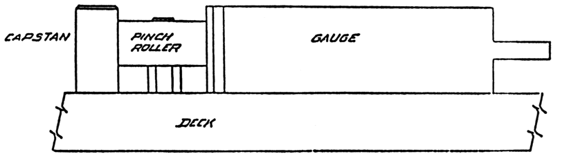
Motor in Correct Position
Figure 7A
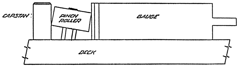
Move Motor Back
Figure 7B
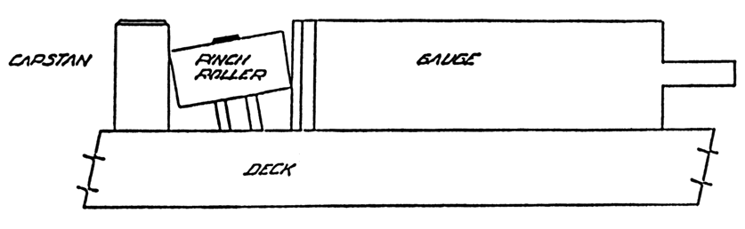
Move Motor Forward
Figure 7C
- Carefully tighten the motor mounting screws using care not to change the motor position.
[End of 3/21/85 Addendum]
4.2 Solenoid Plunger Adjustment
The following adjustments are necessary if the solenoid has been removed.
- Loosen the locking nut on the solenoid plunger and turn the cleaning switch to the on position. Turn the AC power switch on.
- Start the machine without a cartridge.
- If the solenoid does not bottom (no audible noise) stop the machine and rotate the plunger 1/2 turn clockwise. If the solenoid hits bottom go to step E.
- Repeat steps B and C until the solenoid bottoms.
- Stop the machine and rotate the plunger 1/4 turn counterclockwise.
- Start the machine.
- Repeat steps E and F until no audible noise is heard.
- Rotate the plunger an additional 1 1/2 turns counterclockwise.
- Tighten the plunger locking nut and turn off the cleaning switch.
4.3 Solenoid Damping Adjustment
The speed at which the solenoid engages and releases the pressure roller is determined by the air escape valve on the rear of the solenoid. The audible noise generated by the operation of the solenoid is proportional to the speed of the solenoid. The air escape valve may be adjusted by turning the screw at the rear of the solenoid. Turning the screw clockwise will restrict air flow and reduce audible solenoid noise.
4.4 Cartridge Guidance System Alignment
Maximum system performance can only occur if the cartridge is consistently placed in the proper position each time it is inserted. There are three cartridge reference surfaces:
Deck Plate
The cartridge should lie flat on the deck plate. Downward pressure is applied along the left and right cartridge edge because the shell of the cartridge is the strongest along the left and right edges and the hold-down force serves to flatten, rather than warp the cartridge.Head Bridge
When properly inserted, the front of the cartridge should seat squarely against the front of the head bridge. For this reason, tape guide screws, which vary widely and wear uneven indentations in the front of the cartridge, have been eliminated.Right Cartridge Guide
When properly inserted, the cartridge should seat squarely against the right cartridge guide. Slight pressure along the left edge of the cartridge to hold it against the right cartridge guide is desirable.
While the deck plate point is fixed and not adjustable, the head bridge and the right cartridge guide interrelate and are adjusted together.
- Refer to figure 7 and scribe a cartridge as shown.
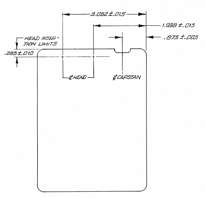
Figure 7
- Remove the head shield by loosening the retaining screws in the front panel and head bridge.
- Slowly insert the cartridge into the machine. If the scribed lines do not line up as shown, or if the cartridge does not seat squarely against the front of the head bridge and the right cartridge guide, realignment is necessary.
- Loosen (DO NOT REMOVE) the deck mounting screws on the right cartridge guide. Position the cartridge and right cartridge guide, while holding them tightly together, until the scribed lines are located over the center of the heads. Be certain that the cartridge seats firmly and squarely against the front of the head bridge. Tighten the right cartridge guide screws while making certain that the cartridge guide does not move.
- As a final test, remove and re-insert the cartridge while holding the cartridge firmly against the right cartridge guide. The cartridge should seat squarely against the front of the head bridge and the scribed lines should be aligned above the center of the head bridge.
NOTE: The above alignment is extremely important for proper azimuth and stereo phase repeatability. Make certain that the cartridge position is adjusted as carefully as possible. When completed, reinstall the head shield.
4.5 Head Bridge Adjustments
Head bridge adjustment includes setting the tracking height, zenith and azimuth on each head, and the tape guide height on each guide (figure 8).
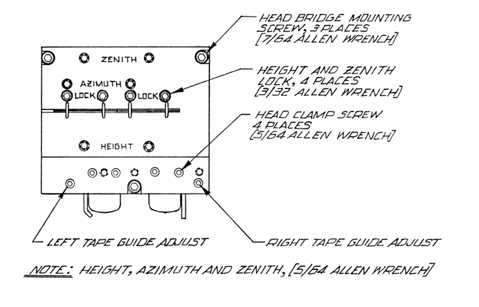
Figure 8
4.5.1 Height and Zenith Adjustment
- Remove the head shield by loosening the front panel and head bridge retaining screws.
- Loosen the height/zenith locking screws by turning them counterclockwise.
- Position the Tape Guide/Head alignment gauge (P/N 710-AO-000 [Revised part was 710-AO-001, possibly also HC-1]) against the front of the tape head. Turn the height adjustment until the top edge of the upper pole piece is even with the top edge of the gauge.
- Turn the zenith adjustment until the front of the tape head is parallel to the front of the gauge.
- Repeat steps C and D until both height and zenith are correct.
- Carefully and equally tighten the lock screws. Recheck the height and zenith adjustments and repeat steps C through F making necessary but slight corrections.
- Repeat for the other tape head.
NOTE: Read Section 4.5.2 before replacing the head shield.
4.5.2 Tape Guide Adjustment
- Remove the head shield by loosening the front panel and head bridge retaining screws.
- Using the Tape Guide/Head Alignment gauge, align the tape guides by turning the tape guide adjustment screw until the inside edge of the upper guide finger just contacts the tip of the height gauge. Repeat for the other guide.
NOTE: Worn guides will seriously affect stereo phase performance. Guides should be checked periodically for signs of wear and replaced when necessary.
- Replace the head shield after adjusting both guides.
4.6 Head Azimuth Adjustment
Before making these adjustments, insure proper alignment as outlined in Sections: 4.1, 4.4, 4.5.1 and 4.5.2. Proper alignment is necessary for machine-to-machine and cart-to-cart compatibility.
NOTE: To avoid possible damage to test tapes, the record and play heads should be carefully degaussed before proceeding. Prior to degaussing, turn AC power switch to off.
4.6.1 Monophonic Play Head Azimuth
- Connect a 600 ohm load to the reproducer output and connect a high impedance voltmeter across the load.
- While reproducing an azimuth alignment tape, adjust the play head azimuth screw for a peak reading on the voltmeter.
4.6.2 Monophonic Record Head Azimuth
- Select an erased cartridge of at least 3.5 minutes duration. This cartridge should be in good working order and representative of the cartridges presently used by your facility.
- Connect a 600 ohm load to the reproducer output and connect a high impedance voltmeter across the load.
- Connect an external 16 kHz oscillator to the record input.
- Insert the cartridge and press the RECORD button.
- Adjust the oscillator for a −10 VU reading on the front panel VU meter.
- Start the machine and adjust the record head azimuth screw for a peak reading on the external voltmeter.
If an external oscillator is not available, the internal test oscillator may be used:
- Remove the mu-metal circuit board cover and place S4 on the tone generator board in the −10 position.
- Set the thumbwheel test oscillator frequency switch on the tone generator board to position 12.
- Connect a 600 ohm load to the reproducer output and connect a high impedance voltmeter across the load.
- Insert the cartridge and press the RECORD button.
- Adjust the TEST OSC level control on the TONE GENERATOR board for a −10 VU reading on the front panel VU meter.
- Start the machine and adjust the record head azimuth for a peak reading on the external voltmeter.
- Place S4 on the TONE GENERATOR board in the center OFF position.
- Replace the mu-metal cover.
NOTE: Retain this cartridge as your record azimuth standard. All machines should be aligned using the same cartridge.
4.6.3 Stereo Play Head Azimuth
- Connect a 600 ohm load to both the left and right reproducer outputs. Connect a high impedance voltmeter across the left channel load.
- Connect the left channel reproducer output to the vertical input of an oscilloscope. Connect the right channel reproducer output to the horizontal oscilloscope input.
- While reproducing a Stereo Fast Sweep Tape (Fidelipac P/N 456), adjust the play head azimuth for an in-phase display on the oscilloscope (fig. 9a). The in-phase setting should coincide with a peak reading on the voltmeter.
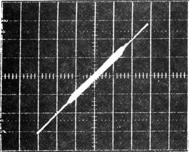
In-phase display
Figure 9a
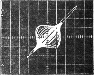
Out-of-phase display
Figure 9b
4.6.4 Stereo Record Head Azimuth
- Select an erased cartridge of at least 3.5 minutes duration. This cartridge should be in good working order and representative of the cartridges presently used by your facility.
- Connect a 600 ohm load to both the left and right reproducer outputs. Connect a high impedance voltmeter across the left channel load.
- Connect the left channel reproducer output to the vertical input of an oscilloscope. Connect the right channel reproducer output to the horizontal oscilloscope input.
- Connect an audio oscillator to both left and right record inputs. Set the oscillator frequency to 16 kHz.
- Insert the cartridge, press the RECORD button and adjust the oscillator level for a −10 dB VU reading on the front panel meters.
- Start the machine and adjust the record head azimuth for a peak reading on the external voltmeter.
- Change the oscillator frequency to 500 Hz and adjust the record head azimuth for an in-phase display on the oscilloscope.
- Slowly increase the oscillator frequency from 500 Hz to 16 kHz. Continue to make slight record head azimuth adjustments to maintain an in-phase display. The higher the frequency, the more critical the azimuth adjustment.
If an external oscillator is not available, the internal test oscillator may be used:
- Remove the mu-metal circuit board cover and place S4 on the tone generator board in the −10 position.
- Set the thumbwheel test oscillator frequency switch on the tone generator board to position 12.
- Connect a 600 ohm load to both the right and left reproduce outputs. Connect a high impedance voltmeter across the left channel load.
- Connect the left reproduce output to the vertical input of an oscilloscope. Connect the right reproducer output to the horizontal oscilloscope input.
- Insert the cartridge, press the RECORD button and adjust the TEST OSC level control for a −10 VU reading on the front panel VU meter.
- Start the machine and adjust the record head azimuth for a maximum reading on the external voltmeter.
- Set the thumbwheel switch to position 5 and adjust the record head azimuth for an in-phase display on the oscilloscope.
- Set the thumbwheel switch to the next higher position and adjust the record head azimuth for an in-phase display on the oscilloscope. Repeat until the thumbwheel switch is set to position 12.
- Place S4 on the TONE GENERATOR board in the center OFF position.
- Replace the mu-metal cover.
NOTE: Retain this cartridge as your record azimuth standard. All machines should be aligned using the same cartridge.
4.6.5 Tape Head Replacement
The tape heads are clamped into the head bracket. To remove a tape head, loosen the clamping screws and gently pull the head forward. Use care not to bend the pins when removing the leads from the tape head. Be certain not to reverse polarity of any connections when reconnecting the new head. When installing a new head, insert it into the clamp as far as possible and tighten the clamp screws.