
Astute viewers will note that the picture quality on this page reverts back to the poor quality of the photos of the original plumbing and conduit installations. The 5 megapixel Canon A95 camera used on the last couple of pages belongs to my father, and he sometimes actually likes to use his camera![]() . I had to revert to my 0.3 megapixel 1997 Apple QuickTake 200 camera for most of the photos on this page. The one exception will be quite obvious.
. I had to revert to my 0.3 megapixel 1997 Apple QuickTake 200 camera for most of the photos on this page. The one exception will be quite obvious.
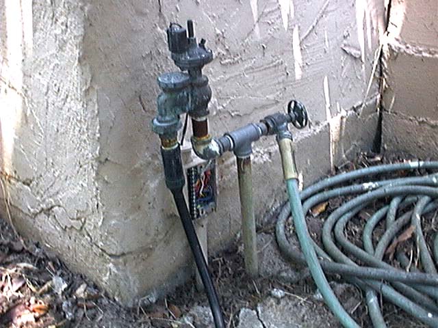
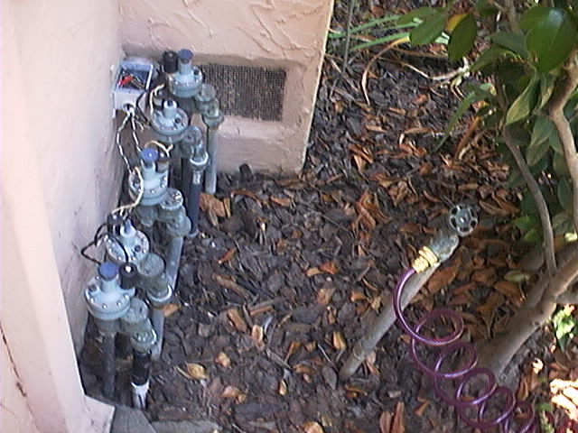
 As noted, upon initial installation the fancy new ET controller controlled nothing other than the one valve on the back corner of the garage feeding the garage rose bed drip circuit (shown in the picture on the left). While the conduit had been in place since 2002, there had been no need to use it with the fleet of three old, separate controllers, and no wire had been purchased or pulled.
I had hoped that careful shopping across a wide range of outlets, including electronics suppliers as well as hardware/irrigation, online and local, would reveal a well-priced single cable meeting my needs: a total of 322 feet of 13 conductors (14 or 15 OK) of 18 or 20 ga. each. (I calculated the voltage drop for the needed length with worst-case current draw and highest dropout voltage figures from actual measurements on the existing valves to be served, and 22 ga. and smaller is too small.) These cables exist, yet the cost of buying enough 100' 7 conductor 18 ga. irrigation cable rolls from Home De(s)pot and doubling them up for 14 conductors was a no-brainer price-wise… even though the sunlight resistant insulation would be totally wasted in my conduit runs. While not as elegant or aesthetically pleasing in terms of insulation color differentiation and having one outer jacket, it is fully serviceable and far, far less expensive than any single cable i could find.
Installing the cable was nearly as easy as would be expected, given the careful design of the conduit system. Due to the cable being made of solid wires, it was not quite as flexible as would have been optimal, yet we got the job done.
 Using my handy documentation of the installation, it was easy to measure out to the conduit bodies buried in the lawn to dig down and remove their covers. Pilot string made it easy to pull the electrical snake backward between pull points, then add the two cable ends and pull them and the string back forward through the conduit together. The biggest challenge was making the 90° corner in the south end middle of the backyard lawn. This was definitely a two-person job (thanks, Siber Hussy!).
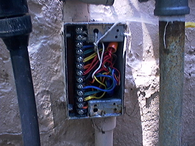
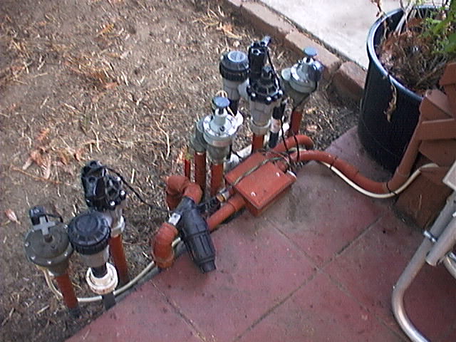
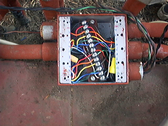
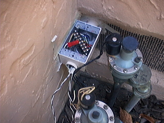
Once pulled, the cables were attached to the appropriate terminals of terminal strips in junction boxes at the garage southwest rear corner, the backyard valve area, and the front yard valve area, shown in the paired photos on each side of this page (overviews on the left or top, closeups on the right or bottom). The wiring follows the color code show in the illustration below. Two lengths of cable were free-run in the garage, fastened by staples, between the controller and the entrance of the conduit system at the rear of the garage junction box.
 Once the conduit enters the house basement, it terminates and the one cable serving the front yard free runs, stapled along the beams etc., to the front of the house. It then pops into a short nipple and into a junction box, for weather protection, ease of repair, ease of troubleshooting, and elegant design, in that order from most important to least.
The wire nut in the closeup picture (right) is used once again because the several common wires are too much to fit under one screw head with any sort of reliability, so a bigger wire “stubs out” from the screw head to the wire nut.
 (If you want to actually be able to see the wiring, you’ll very likely want to click the picture to open up a full-size version in a new window.)
Having an extra conductor not otherwise occupied, i selected red (no band) wire to be an always-hot wire, useful for using a jumper wire to quickly activate a valve, for testing purposes. The wiring is all in place except at the controller, where i am waiting for a warranty extension to wrap up before making a warranty-voiding modification to access the needed always-on connection. Having not anticipated this use when purchasing the terminal strips, this wire is wire-nutted (visible in some of the pictures) at some junction boxes. There are also some wire nuts used for the common wires of the valves, which as mentioned are too plentiful and thick to fit directly under the terminal strip screw heads. Hence, a short, thick piece of wire links the terminal screw with the wire nut.
All wires and all zones on the controller are wired up for use. Zone #9 is reserved for the possible extra valve which can be added to the backyard manifold if needed. All wired up, yet no valve. Set for zero run time on the controller.
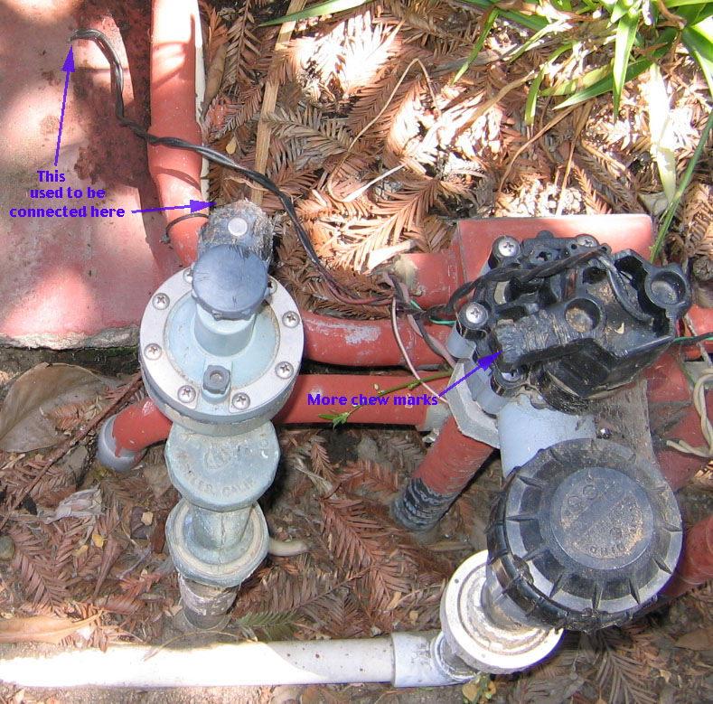
Even with all those wires and connection points, there were only one or two wiring errors detected and corrected during initial inspection and testing. Since then, the wiring has worked flawlessly, in no small part thanks to protection from the weather. There have been one or two valve solenoids destroyed by squirrels (apparently they like eating some plastics) and some bugs with the Accurate WeatherSet controller, otherwise the system has run flawlessly since installation. (I intend to make a nice [albeit heavy] sitting bench out of a collection of surplus glass bricks we happen to have, to cover the backyard valves, yet it has not happened yet.)
That’s all for the ![]() controller section, and in fact for all of
controller section, and in fact for all of ![]() Extreme Irrigation Electrical. Would you like to finish up by
Extreme Irrigation Electrical. Would you like to finish up by  Seeing the lawns and gardens after the Extreme Irrigation project concluded…?
 World O’ Appliances/Household/Plumbing/Irrigation/HVAC/Hardware
![]() The Sonically Pure Pages
The Sonically Pure Pages
This Siber-Sonically Pure Page is ![]() and
and ![]() Transitional compliant.
Transitional compliant.