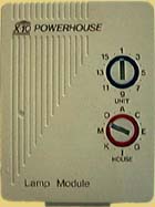
LM465 Lamp Module and Similar Modules
It is difficult to pick which representative module from amongst the myriad of choices in the X10 lineup to use to describe the alignment procedure. While i have rather arbitrarily chosen the LM465 Lamp Module, the same principles apply to other X10 receiving modules (at least the older, one-way flavor i use), so hopefully you will have no problem modifying the instructions to match what you have.
Repair
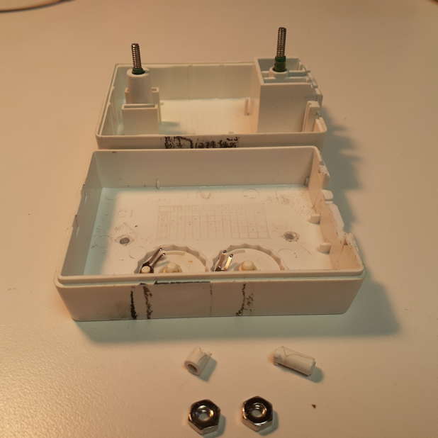
Case Repair
As with many products, X10 plastics weren’t necessarily designed to last for decades: breakage is common. Site correspondent Steve experienced this issue with the plastic screw posts in several of his modules, and shares pictures of his fix:
Functional, reliable, reasonably easy… works for me!
Module Alignment
To ensure successful alignment, please be sure to read important information common to all X10 alignment procedures before proceeding.
PLC Input Sensitivity Adjustment
- Disassemble the module (usually 2 to 4 screws). It is O.K. to either leave the front cover (with the House and Unit code dials) in place, or remove both covers and work with a bare PCB. Attach a very short extension cord, if needed, to allow for adjustment while module is powered.
- Move the module to the location where it will be used. Bring along oscilloscope, isolation transformer (if needed), and previously calibrated controller of known correct frequency.
- Connect the controller to a separate circuit, or at least an electrically distant outlet on the same circuit, via some means of attenuating its 120kHz output (see the discussion in Common Points... for suggestions).
- Connect oscilloscope 10X probe to pin 1 of 78570 IC (i like to use the 33pF capacitor lead which attaches to pin 1), probe ground to circuit common (the narrower of the two A.C. prongs, i.e. “Hot”). Oscilloscope must be isolated from the A.C. powerline, since module must be directly connected for best results. Avoid touching oscilloscope while module is powered. I usually start with 10mV/div (X10=.1V/div actual), and 5µsec sweep.
- Connect LM465 directly to the A.C. line.
- Key controller to generate a continuous signal (Bright or Dim achieve this on most controllers so equipped).
- Inspect waveform. If there is clipping, reduce the amplitude of the signal from the controller until the displayed waveform is sinusoidal.
- Adjust module transformer for maximum 120kHz signal amplitude. This is likely to be a broad, “low-Q” peak.
- Unplug/disconnect all.
- Reassemble module and test.
Questions/comments may be addressed to: Sonic Purity