 IMPORTANT: This information is provided AS-IS, for informational purposes only, with no warranty whatsoever.
 Neither Sonic Purity nor anyone at Siber-Sonic.com can control your ability to successfully and safely utilize this information, and we accept no responsibility for anyone’s actions (beyond our own) related to the content of this website. X10 equipment utilizes the A.C. power line, which is
dangerous. Do not attempt any of these adjustments if you have any doubt about your ability to work safely with household powerline-operated devices. It is your responsibility to know and understand common safety procedures, especially those involving electricity at potentially dangerous power levels!
Required Equipment
- Oscilloscope with 10X probe, preferably powerline-isolated.
- Frequency counter, preferably powerline-isolated. 120kHz for PLC, 310MHz for R.F. adjustment.
- Isolation transformer if either or both of the above are powerline-operated and not sufficiently isolated.
- Various screwdrivers and alignment tools for both iron/ferrite transformer slugs and trimpots.
- Some means to monitor 120kHz across the A.C. line without appreciably loading the X10 device under test.
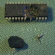
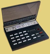
WARNING: Always be aware of what amongst your particular test equipment needs isolation. Here is what momentarily forgetting what i was doing did to the IC from an older Maxi-controller:
Luckily, it blew up the <$30 maxi-controller, and not the >$300 powerline-operated frequency counter!
In each individual alignment procedure, i will mention isolation devices as i used them with my equipment. It is up to you to modify my instruction to pertain to your particular equipment. Depending what you have, you may not need isolation where i needed it, or vice-versa. Proceed with caution!
Basic adjustment outline
- Adjust a wired controller, to use as a reference
- Adjust PLC frequency
- Adjust PLC output amplitude at location of final use
- Repeat for other controllers
- Adjust PLC input sensitivity at locations of final use for all modules
- Adjust R.F. devices
Output amplitude needs to be measured in some way away from the module, to minimize the interaction of the test equipment. At first, i used a 16VAC step-down transformer for controller output amplitude adjustments. The 120kHz signal was hard to find and trigger. After smoking the maxi-controller, i disabled most of the few remaining parts to utilize what was the 120kHz output transformer resonant circuit as a 120kHz filter. Tried it via the step-down transformer: signal was too weak. Connected via an isolation transformer, it worked great! In the future, i hope to provide a schematic of a full-fledged X10 alignment box here at siber-sonic.com. Until then, i leave you to your ingenuity as to how you will safely measure the PLC output on X10 controllers. For the purposes of these alignment pages, i will already refer to whatever 120kHz sensing arrangement may be used as the “powerline signal sensor”.
In some cases, the PLC frequency will be measured from the powerline signal sensor, just as for the amplitude. This will usually be in cases where it is possible to generate the 120kHz carrier without the X10 data stream modulation. In other cases, the 120kHz carrier, or some clock multiple thereof, will be measured directly on the device being adjusted, where this can be done without detuning the oscillator!
PLC receive amplitude in controlled modules will be measured within the module. It will be necessary to attenuate the output of a previously-aligned (for correct frequency, at least) controller sufficiently to put the received signal below the diode clipping amplitude, yet large enough to see above the noise reliably. It would be very convenient to have a modified controller with continuously-adjustable output amplitude. Having not thought of that as i was developing these alignment procedures, i used two other methods to attenuate the signal from the reference X10 controller:
- powering the controller through a variable A.C. autotransformer (Variac®) and reducing A.C. input as necessary
- connecting the controller to a long extension cord (15 to 30m/50 to 100') and adding/removing loops and/or changing to other circuits to obtain a reasonable amplitude
Surprisingly, i found the latter method to be both easier and faster than dragging around the heavy autotransformer.
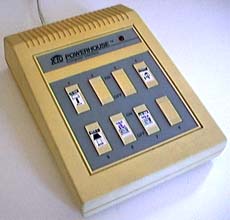
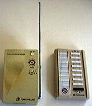
Now that you have an overall sense of what is going on, pick from amongst the following selections for specific alignment instructions for specific X10 devices:
 IMPORTANT: This information is provided AS-IS, for informational purposes only, with no warranty whatsoever. Neither Sonic Purity nor anyone at Siber-Sonic.com can control your ability to successfully and safely utilize this information, and we accept no responsibility for anyone’s actions (beyond our own) related to the content of this website. X10 equipment utilizes the A.C. power line, which is dangerous. Do not attempt any of these adjustments if you have any doubt about your ability to work safely with household powerline-operated devices. It is your responsibility to know and understand common safety procedures, especially those involving electricity at potentially dangerous power levels!
