Originally written and posted 2 June 2001
Content last modified
Saturday, 9 January 2021
External links last verified Friday, 8 June 2018
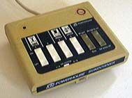
I happen to have two SD533 Sundowners and no MC460 Mini Controllers. I strongly suspect that most everything i have to say here applies to both. And i don’t really have too much to say, since the Sundowners have been very reliable for me (once positioned correctly!).
After nearly two decades of reliable operation, in summer 2012 one of our Sundowner Mini-Controllers failed. The symptom was that the built-in LED showed normal operation, but it was not possible to control any modules, even one immediately adjacent to the controller.
Usually, this sort of failure is a switch problem: dirty contacts so that the house code or unit bank signal being sent out does not match the actual switch position. I verified that this was not the problem.
The rest of this discussion will refer to the schematic for the MC460 Mini Controller (originally found on Ido Bartana’s site, more recently on Tom’s Home Automation Webpage), since i have not easily found an online schematic for the SD533. The circuit is the same for the base unit; only the light detection functions (on a separate PCB) differ.
I found that there was insufficient PLC signal coming out of the unit. Frequency was correct at 120 kHz on IC U1 pin 4 (holding down Bright for continuous PLC signal). On an oscilloscope, one should see an approx. 17Vp-p square wave here, with the baseline at circuit common (ground). On the base of Q1, this same signal is voltage divided by R8 and R7 to approx. 2.9Vp-p. When everything is working, the collector of Q1 should have a distorted (esp. at the bottom) sine wave of approx. 28Vp-p, again with the bottom of the sine wave at circuit common voltage (0V w.r.t. common). I found a very distorted and shifting 1Vp-p square wave instead.
Normal troubleshooting eventually revealed that 1.5 nF polypropylene capacitor C6 had shorted. Replacing this capacitor restored normal operation. I readjusted T1 for maximum signal, but the change was insignificant.
In late 2013, this same controller developed the same symptoms. At first it still controlled some modules, but not all. Soon thereafter, it ceased controlling any modules. This time, there was basically no PLC signal out of the SD533. I finally opened it up and troubleshot it at the beginning of 2014, expecting to find C6 failed again. Nope: coupling capacitor C3 was at fault this time, having lost a great deal of capacity, as i verified by paralleling a similar capacitor to restore operation. The schematic lists it as “220n MY”, their way of saying 220nF, a.k.a. 0.22µF mylar capacitor. The existing part in mine was rated at 250V, and that’s the lowest safe D.C. voltage rating i’d recommend for a 120V Sundowner (or Mini Controller). I happened to have an A.C.-rated safety agency approved .22µF mylar capacitor rated for 125 VAC. Installed it, tweaked T1 (didn’t really matter) and this particular Sundowner again seems to be working.
To ensure successful alignment, please be sure to read important information common to all X10 alignment procedures before proceeding.
World O’ X10 ![]()
![]() The Sonically Pure Pages
The Sonically Pure Pages
This Siber-Sonically Pure Page is ![]() and
and ![]() Transitional compliant.
Transitional compliant.